57621-92D01 CLUTCH DOG SHIFTER Suzuki
DT8CENK, DT8CENL, DT8CLJ, DT8CLK, DT8CLL, DT8CLM, DT8CNK, DT8CNL, DT8CSJ, DT8CSL, DT8CSM, DT8MCLN, DT8MCLP, DT8MCLS, DT8MCLT, DT8MCLV, DT8MCSN, DT8MCSP, DT8MCSR, DT8MCSS, DT8MCST, DT8MCSV, DT8MSLR, DT8SCK, DT9.9 CELK, DT9.9CELJ, DT9.9CELL, DT9.9CELM,
CLUTCH

Price: query
Rating:
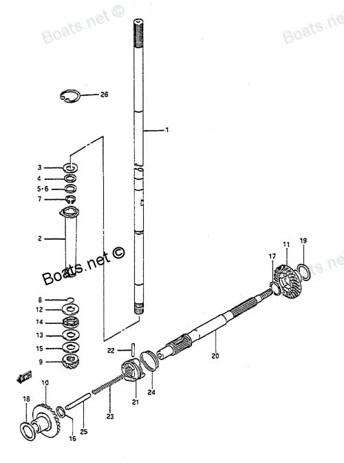
Number on catalog scheme: 21
Compatible models:
DT8CENK
DT8CENL
DT8CLJ
DT8CLK
DT8CLL
DT8CLM
DT8CNK
DT8CNL
DT8CSJ
DT8CSL
DT8CSM
DT8MCLN
DT8MCLP
DT8MCLS
DT8MCLT
DT8MCLV
DT8MCSN
DT8MCSP
DT8MCSR
DT8MCSS
DT8MCST
DT8MCSV
DT8MSLR
DT8SCK
DT9.9 CELK
DT9.9CELJ
DT9.9CELL
DT9.9CELM
DT9.9CELN
DT9.9CELP
DT9.9CELR
DT9.9CELS
DT9.9CELT
DT9.9CENK
DT9.9CESJ
DT9.9CESK
DT9.9CESL
DT9.9CESM
DT9.9CESN
DT9.9CESP
DT9.9CESR
DT9.9CESS
DT9.9CEST
DT9.9CNELP
DT9.9CNELR
DT9.9CNELS
DT9.9CNELT
DT9.9CNEXP
DT9.9CNEXR
DT9.9CNEXS
DT9.9CNEXT
DT9.9CNEXV
DT9.9CNJ
DT9.9CNK
DT9.9CNL
DT9.9CNLN
DT9.9MCLJ
DT9.9MCLK
DT9.9MCLL
DT9.9MCLM
DT9.9MCLN
DT9.9MCLP
DT9.9MCLR
DT9.9MCLS
DT9.9MCLT
DT9.9MCLV
DT9.9MCNLR
DT9.9MCNLT
DT9.9MCNLV
DT9.9MCSJ
DT9.9MCSK
DT9.9MCSL
DT9.9MCSM
DT9.9MCSN
DT9.9MCSP
DT9.9MCSR
DT9.9MCSS
DT9.9MCST
DT9.9MCSV
Suzuki
Suzuki entire parts catalog list:
- TRANSMISSION » 57621-92D01
- TRANSMISSION » 57621-92D01
- TRANSMISSION » 57621-92D01
- TRANSMISSION » 57621-92D01
- TRANSMISSION » 57621-92D01
- TRANSMISSION » 57621-92D01
- TRANSMISSION » 57621-92D01
- TRANSMISSION » 57621-92D01
- TRANSMISSION » 57621-92D01
- TRANSMISSION » 57621-92D01
- TRANSMISSION » 57621-92D01
- TRANSMISSION » 57621-92D01
- TRANSMISSION » 57621-92D01
- TRANSMISSION » 57621-92D01
- TRANSMISSION » 57621-92D01
- TRANSMISSION » 57621-92D01
- TRANSMISSION » 57621-92D01
- TRANSMISSION » 57621-92D01
- TRANSMISSION » 57621-92D01
- TRANSMISSION » 57621-92D01
- TRANSMISSION » 57621-92D01
- TRANSMISSION » 57621-92D01
- TRANSMISSION » 57621-92D01
- TRANSMISSION » 57621-92D01
- TRANSMISSION » 57621-92D01
- TRANSMISSION » 57621-92D01
- TRANSMISSION » 57621-92D01
- TRANSMISSION » 57621-92D01
- TRANSMISSION » 57621-92D01
- TRANSMISSION » 57621-92D01
- TRANSMISSION » 57621-92D01
- TRANSMISSION » 57621-92D01
- TRANSMISSION » 57621-92D01
- TRANSMISSION » 57621-92D01
- TRANSMISSION » 57621-92D01
- TRANSMISSION » 57621-92D01
- TRANSMISSION » 57621-92D01
- TRANSMISSION » 57621-92D01
- TRANSMISSION » 57621-92D01
- TRANSMISSION » 57621-92D01
- TRANSMISSION » 57621-92D01
- TRANSMISSION » 57621-92D01
- TRANSMISSION » 57621-92D01
- TRANSMISSION » 57621-92D01
- TRANSMISSION » 57621-92D01
- TRANSMISSION » 57621-92D01
- TRANSMISSION » 57621-92D01
- TRANSMISSION » 57621-92D01
- TRANSMISSION » 57621-92D01
- TRANSMISSION » 57621-92D01
- TRANSMISSION » 57621-92D01
- TRANSMISSION » 57621-92D01
- TRANSMISSION » 57621-92D01
- TRANSMISSION » 57621-92D01
- TRANSMISSION » 57621-92D01
- TRANSMISSION » 57621-92D01
- TRANSMISSION » 57621-92D01
- TRANSMISSION » 57621-92D01
- TRANSMISSION » 57621-92D01
- TRANSMISSION » 57621-92D01
- TRANSMISSION » 57621-92D01
- TRANSMISSION » 57621-92D01
- TRANSMISSION » 57621-92D01
- TRANSMISSION » 57621-92D01
- TRANSMISSION » 57621-92D01
- TRANSMISSION » 57621-92D01
- TRANSMISSION » 57621-92D01
- TRANSMISSION » 57621-92D01
- TRANSMISSION » 57621-92D01
- TRANSMISSION » 57621-92D01
- TRANSMISSION » 57621-92D01
- TRANSMISSION » 57621-92D01
- TRANSMISSION » 57621-92D01
- TRANSMISSION » 57621-92D01
- TRANSMISSION » 57621-92D01
- TRANSMISSION » 57621-92D01
- TRANSMISSION » 57621-92D01
- TRANSMISSION » 57621-92D01
- TRANSMISSION » 57621-92D01
Information:
Grounding Practices
Proper grounding for the electrical system is necessary for proper engine performance and reliability. Improper grounding will result in unreliable electrical circuit paths and in uncontrolled electrical circuit paths.Uncontrolled engine electrical circuit paths can result in damage to the main bearings, to the crankshaft bearing journal surfaces, and to the aluminum components.Uncontrolled electrical circuit paths can cause electrical noise which may degrade performance.In order to ensure proper functioning of the electrical system, an engine-to-frame ground strap with a direct path to the battery must be used. This may be provided by the starting motor ground, by a frame to starting motor ground, or by a direct frame to engine ground. An engine-to-frame ground strap must be run from the grounding stud of the engine to the frame and to the negative battery post.
Illustration 1 g01486733
Typical example of grounding the battery and the cylinder head to the frame rail
(1) Cylinder head ground stud
(2) Optional engine ground stud
(3) Frame rail Connect the battery negative post to frame rail (3). From the frame rail, connect the ground wire to one of the following locations:
Cylinder head ground stud (1)
Optional engine ground stud connection (2)
Illustration 2 g01096929
Typical example of the alternate cylinder head to the battery ground
(1) Cylinder head ground stud
(2) Optional engine ground stud
(3) Frame rail The engine must be grounded to frame rail (3). Connect the battery negative post to one of the following locations:
Cylinder head ground stud (1)
Optional engine ground stud connection (2)The engine must have a ground wire to the battery.Ground wires or ground straps should be combined at the studs that are only for ground use.All of the ground paths must be capable of carrying any potential currents. A wire that is AWG 0 or more is recommended for the cylinder head ground strap.The engine alternator should be grounded to the battery with a wire size that is capable of managing the full charging current of the alternator.
When jump starting an engine, the instructions in the Operation and Maintenance Manual, "Starting with Jump Start Cables" should be followed in order to properly start the engine.This engine may be equipped with a 12 volt starting system or with a 24 volt starting system. Only equal voltage for boost starting should be used. The use of a welder or of a higher voltage will damage the electrical system.
The engine has several input components which are electronic. These components require an operating voltage.This engine is tolerant to common external sources of electrical noise. Electromechanical buzzers can cause disruptions in the power supply. If electromechanical buzzers are used near the system, the engine electronics should be powered directly from the battery system through a dedicated relay. The engine electronics should not be powered through a common power bus with other devices that are activated by the engine control switch (ECS).Engine Electrical System
The electrical system can have three separate circuits. The three circuits are the charging circuit, the starting circuit, and the low amperage circuit. Some of the electrical system components are used in more than one circuit.The charging circuit is in operation when the engine is running. An alternator creates electricity for the charging circuit. A voltage regulator in the circuit controls the electrical output in order to maintain the battery at full charge.The starting circuit is in operation when the start switch is activated.The low amperage circuit and the charging circuit are connected through the ammeter. The starting circuit is not connected through the ammeter.Charging System Components
Alternator
The alternator is driven by the crankshaft pulley through a belt that is a Poly-vee type. This alternator is a three-phase self-rectifying charging unit. The regulator is part of the alternator.The alternator design has no need for slip rings or for brushes. The only part of this alternator that moves is the rotor assembly. All of the conductors that carry current are stationary. The following components are the conductors: the field winding, the stator windings, six rectifying diodes and the regulator circuit.The rotor assembly has many magnetic poles with air space between each of the opposite poles. The poles have residual magnetism that produces a small amount of magnet-like lines of force (magnetic field). This magnetic field is produced between the poles. As the rotor assembly begins to turn between the field winding and the stator windings, a small amount of alternating current (AC) is produced in the stator windings. The alternating current is produced from the small magnetic lines of force that are created by the residual magnetism of the poles. The AC is changed into direct current (DC) when the current passes through the diodes of the rectifier bridge. Most of this current provides the battery charge and the supply for the low amperage circuit. The remainder of current is sent to the field windings. The DC current flow through the field windings (wires around an iron core) increases the strength of the magnetic lines of force. These stronger magnetic lines of force increase the amount of AC that is produced in the stator windings. The increased speed of the rotor assembly also increases the current output of the alternator and the voltage output of the alternator.The voltage regulator is a solid-state electronic switch. The voltage regulator senses the voltage of the system. The regulator then uses switches to control the current to the field windings. This controls the voltage output in order to meet the electrical demand of the system.
The alternator should never be operated without the battery in the circuit. The making or the breaking of an alternator connection with a heavy load on the circuit can cause damage to the regulator.
Illustration 3 g01486777
Typical cross section of an alternator
(4) Regulator
(5) Roller bearing
(6) Stator winding
(7) Ball bearing
(8) Rectifier bridge
(9) Field winding
(10) Rotor assembly
(11) Fan Starting System Components
Solenoid
Illustration 4 g00292316
Typical cross section of a solenoid
A solenoid is an electromagnetic switch that performs two basic functions:
The solenoi
Parts clutch Suzuki:
21110-93912
21110-93912 CLUTCH LEVER
DT8CENK, DT8CENL, DT8CLJ, DT8CLK, DT8CLL, DT8CLM, DT8CNK, DT8CNL, DT8CSJ, DT8CSL, DT8CSM, DT8MCLN, DT8MCLP, DT8MCLS, DT8MCLT, DT8MCLV, DT8MCSN, DT8MCSP, DT8MCSR, DT8MCSS, DT8MCST, DT8MCSV, DT8MSLR, DT8SCK, DT9.9 CELK, DT9.9CELJ, DT9.9CELL, DT9.9CELM,
23311-95DL0
23311-95DL0 CLUTCH ROD TURNBUCKLE
DF15, DF15, DF15, DF9.9, DF9.9R, DF9.9TH, DF9.9TH, DT30CRLJ, DT30CRSJ, DT30MCLJ, DT30MCSJ, DT8CENK, DT8CENL, DT8CLJ, DT8CLK, DT8CLL, DT8CLM, DT8CNK, DT8CNL, DT8CSJ, DT8CSL, DT8CSM, DT8MCLN, DT8MCLP, DT8MCLS, DT8MCLT, DT8MCLV, DT8MCSN, DT8MCSP, DT8MCS
23111-92D00
23111-92D00 CLUTCH ROD
DT8CENK, DT8CENL, DT8CLJ, DT8CLK, DT8CLL, DT8CLM, DT8CNK, DT8CNL, DT8CSJ, DT8CSL, DT8CSM, DT8MCLN, DT8MCLP, DT8MCLS, DT8MCLT, DT8MCLV, DT8MCSN, DT8MCSP, DT8MCSR, DT8MCSS, DT8MCST, DT8MCSV, DT8MSLR, DT8SCK, DT9.9 CELK, DT9.9CELJ, DT9.9CELL, DT9.9CELM,
21126-92D00
21126-92D00 CLUTCH SHAFT HOLDER
DT15C, DT8CENK, DT8CENL, DT8CLJ, DT8CLK, DT8CLL, DT8CLM, DT8CNK, DT8CNL, DT8CSJ, DT8CSL, DT8CSM, DT8MCLN, DT8MCLP, DT8MCLS, DT8MCLT, DT8MCLV, DT8MCSN, DT8MCSP, DT8MCSR, DT8MCSS, DT8MCST, DT8MCSV, DT8MSLR, DT8SCK, DT9.9 CELK, DT9.9CELJ, DT9.9CELL, DT9
21131-96010
21131-96010 CLUTCH SHIFT MARK
DF100, DF100, DF100, DF115, DF115, DF115, DF115TL, DF15, DF15, DF15S, DF25, DF25(R)S, DF25Q, DF25Q(QR), DF25R, DF25R, DF25T, DF30, DF30Q, DF30Q(QR), DF30T, DF4, DF4, DF4, DF40, DF40, DF40A, DF40A, DF40QH, DF40TL, DF46, DF4L, DF50, DF50, DF50A, DF50A,