51122-93J02 COVER, MOUNT OIL SEAL Suzuki
DF200, DF200, DF200, DF225, DF225, DF225, DF250, DF250, DF250, DF250A, DF300, DF300, DF300A
COVER

Price: query
Rating:
Number on catalog scheme: 43
Suzuki entire parts catalog list:
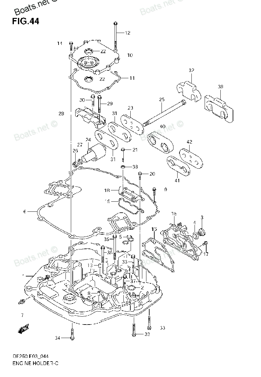
- ENGINE HOLDER » 51122-93J02
- ENGINE HOLDER » 51122-93J02
- ENGINE HOLDER (DF250T) » 51122-93J02
- ENGINE HOLDER (DF225T) » 51122-93J02
- ENGINE HOLDER (DF250Z) » 51122-93J02
- ENGINE HOLDER (DF225Z) » 51122-93J02
- ENGINE HOLDER (DF200T) » 51122-93J02
- ENGINE HOLDER (DF250ST) » 51122-93J02
- ENGINE HOLDER (DF200Z) » 51122-93J02
- ENGINE HOLDER » 51122-93J02
- ENGINE HOLDER » 51122-93J02
- ENGINE HOLDER (DF250ST) » 51122-93J02
- ENGINE HOLDER (DF200Z) » 51122-93J02
- ENGINE HOLDER (DF250T) » 51122-93J02
- ENGINE HOLDER (DF225T) » 51122-93J02
- ENGINE HOLDER (DF250Z) » 51122-93J02
- ENGINE HOLDER (DF225Z) » 51122-93J02
- ENGINE HOLDER (DF200T) » 51122-93J02
- ENGINE HOLDER » 51122-93J02
- ENGINE HOLDER » 51122-93J02
- ENGINE HOLDER » 51122-93J02
- ENGINE HOLDER (310001~) » 51122-93J02
- ENGINE HOLDER (210001~) » 51122-93J02
- ENGINE HOLDER (210001~) » 51122-93J02
Information:
1. Remove the fuel filter housing and oil filter housing support bracket (1). Remove the regulator housing water bypass line mounting bolts (2). Remove aftercooler raw water outlet lines (3). Disconnect jacket water temperature sending unit (4) from regulator housing. Remove water line mounting bolts (5) and (6). 2. Disconnect turbocharger heat shield water return line (12) from regulator housing. Remove fuel bleed line clamp mounting bolt (11). Remove fuel injection pump housing fuel inlet line clamp mounting bolt (9). Remove fuel transfer pump fuel inlet line clamp mounting bolt (10) from engine front lifting bracket. Disconnect wiring from water temperature shutoff sending unit (14).3. Attach a hoist to regulator housing, and remove the two mounting bolts (7). Remove the water temperature regulator housing (8) - weight 130 lbs. (59 kg).4. Disconnect governor control linkage from the governor. Remove channel assembly (13). 5. Remove turbocharger heat shield water outlet lines (15). Remove the two fuel injection pump housing bracket mounting bolts (16) from right cylinder head. Remove fuel ratio control sensing line (17). Remove the governor-to-right aftercooler housing mounting bracket (18). 6. Remove the raw water line-to-exhaust elbow mounting bracket (19). Remove the four exhaust elbow bracket mounting bolts (20), and loosen the four bracket mounting bolts (21). Remove right aftercooler raw water inlet elbow (22).7. Remove the cylinder head retaining nuts and washers. Attach a hoist and remove the right cylinder head assembly - weight 475 lbs. (215 kg). It is not necessary to remove spacer plate unless spacer plate gasket has been leaking or was damaged during removal of cylinder head assembly.Install Right Cylinder Head Assembly
1. Clean the top surface of spacer plate and mating surface of cylinder head. Install the cylinder head gasket and water seals. 2. Attach a hoist and position the cylinder head assembly on engine. Coat the threads of retaining studs with 9M3710 Anti-Seize Compound. Install washers and retaining nuts. Tighten the nuts in following Step sequence: 1 - Tighten all nuts in numerical sequence to 175 lb. ft. (24,2 mkg).2 - Retighten all nuts in numerical sequence to 250 lb. ft. (34,6 mkg).3 - Finally retighten all nuts by hand in numerical sequence to 250 lb. ft. (34,6 mkg). 3. Install the right aftercooler raw water inlet elbow. Install exhaust elbow bracket mounting bolts in right cylinder head, and tighten elbow bracket mounting bolts in left cylinder head. Install raw water line-to-elbow mounting bracket. 4. Install the governor-to-right aftercooler mounting bracket. Install fuel ratio control sensing line. Install the two fuel injection pump housing bracket mounting bolts in right cylinder head. Install turbocharger heat shield water outlet lines.5. Install the governor control channel assembly. Connect control linkage to the governor.6. Attach a hoist and position water temperature regulator housing on engine. Install the two lower housing-to-cylinder head mounting bolts.7. Connect wiring to water temperature shut-off sending unit. Install fuel inlet line clamp mounting bolts in engine lifting bracket and in left aftercooler housing. Install fuel bleed line clamp mounting bolt in right aftercooler housing. Connect turbocharger heat shield water return line to the regulator housing.8. Connect water lines to bottom of lower housing. Connect jacket water temperature sending unit to regulator housing. Install aftercooler raw water outlet lines. Install regulator housing water bypass line mounting bolts. Install the fuel filter housing and oil filter housing support bracket.concluding steps:a) install oil filter housingb) install fuel filter housingc) install turbochargersd) install right camshaft housing
1. Clean the top surface of spacer plate and mating surface of cylinder head. Install the cylinder head gasket and water seals. 2. Attach a hoist and position the cylinder head assembly on engine. Coat the threads of retaining studs with 9M3710 Anti-Seize Compound. Install washers and retaining nuts. Tighten the nuts in following Step sequence: 1 - Tighten all nuts in numerical sequence to 175 lb. ft. (24,2 mkg).2 - Retighten all nuts in numerical sequence to 250 lb. ft. (34,6 mkg).3 - Finally retighten all nuts by hand in numerical sequence to 250 lb. ft. (34,6 mkg). 3. Install the right aftercooler raw water inlet elbow. Install exhaust elbow bracket mounting bolts in right cylinder head, and tighten elbow bracket mounting bolts in left cylinder head. Install raw water line-to-elbow mounting bracket. 4. Install the governor-to-right aftercooler mounting bracket. Install fuel ratio control sensing line. Install the two fuel injection pump housing bracket mounting bolts in right cylinder head. Install turbocharger heat shield water outlet lines.5. Install the governor control channel assembly. Connect control linkage to the governor.6. Attach a hoist and position water temperature regulator housing on engine. Install the two lower housing-to-cylinder head mounting bolts.7. Connect wiring to water temperature shut-off sending unit. Install fuel inlet line clamp mounting bolts in engine lifting bracket and in left aftercooler housing. Install fuel bleed line clamp mounting bolt in right aftercooler housing. Connect turbocharger heat shield water return line to the regulator housing.8. Connect water lines to bottom of lower housing. Connect jacket water temperature sending unit to regulator housing. Install aftercooler raw water outlet lines. Install regulator housing water bypass line mounting bolts. Install the fuel filter housing and oil filter housing support bracket.concluding steps:a) install oil filter housingb) install fuel filter housingc) install turbochargersd) install right camshaft housing
Parts cover Suzuki:
48145-93J00
48145-93J00 COVER, TILT LIMIT SWITCH
DF100, DF100, DF100, DF115, DF115, DF115, DF115TL, DF140, DF140, DF140, DF140T, DF140T, DF140Z, DF140Z, DF140Z, DF140Z, DF150, DF150, DF150, DF150TX, DF150ZX, DF175, DF175, DF175, DF175TX, DF175ZX, DF200, DF200, DF200, DF200T, DF200Z, DF225, DF225, D
61400-93Y60-0EP
61400-93Y60-0EP COVER SET, ENGINE (BLACK)
DF200, DF200, DF200T, DF200Z, DF225, DF225, DF225T, DF225Z, DF250, DF250, DF250T, DF250Z
61400-93Y48-0EP
15644-93J00
15644-93J00 COVER, FUEL FILTER
DF200, DF200, DF200, DF200T, DF200Z, DF225, DF225, DF225, DF225T, DF225Z, DF250, DF250, DF250, DF250A, DF250T, DF250Z, DF300, DF300, DF300A
61811-93J03-0EP
17681-93J00
17681-93J00 COVER, THERMOSTAT
DF200, DF200, DF200, DF200T, DF200Z, DF225, DF225, DF225, DF225T, DF225Z, DF250, DF250, DF250, DF250A, DF250T, DF250Z, DF300, DF300, DF300A
67271-98J20
61811-98J01-0EP