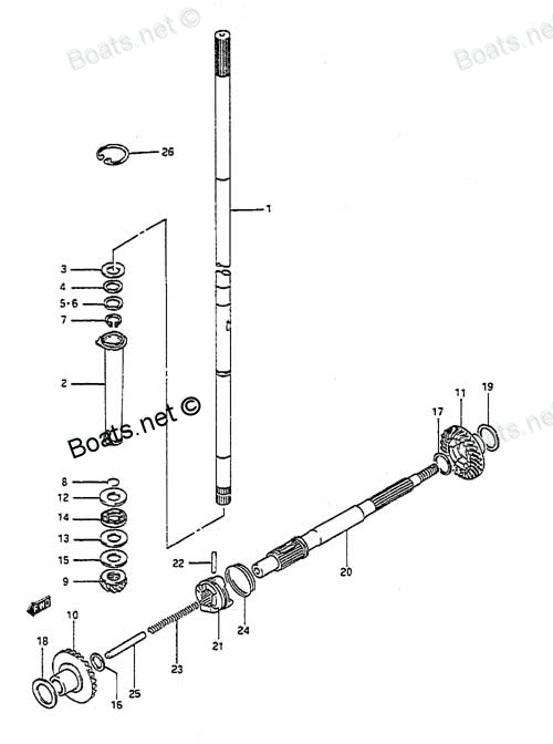
57510-92D00 FORWARD GEAR Suzuki
DT8CENK, DT8CENL, DT8CLJ, DT8CLK, DT8CLL, DT8CLM, DT8CNK, DT8CNL, DT8CSJ, DT8CSL, DT8CSM, DT8MCLN, DT8MCLP, DT8MCLS, DT8MCLT, DT8MCLV, DT8MCSN, DT8MCSP, DT8MCSR, DT8MCSS, DT8MCST, DT8MCSV, DT8MSLR, DT8SCK, DT9.9 CELK, DT9.9CELJ, DT9.9CELL, DT9.9CELM,
FORWARD

Price: query
Rating:
Number on catalog scheme: 10
Compatible models:
DT8CENK
DT8CENL
DT8CLJ
DT8CLK
DT8CLL
DT8CLM
DT8CNK
DT8CNL
DT8CSJ
DT8CSL
DT8CSM
DT8MCLN
DT8MCLP
DT8MCLS
DT8MCLT
DT8MCLV
DT8MCSN
DT8MCSP
DT8MCSR
DT8MCSS
DT8MCST
DT8MCSV
DT8MSLR
DT8SCK
DT9.9 CELK
DT9.9CELJ
DT9.9CELL
DT9.9CELM
DT9.9CELN
DT9.9CELP
DT9.9CELR
DT9.9CELS
DT9.9CELT
DT9.9CENK
DT9.9CESJ
DT9.9CESK
DT9.9CESL
DT9.9CESM
DT9.9CESN
DT9.9CESP
DT9.9CESR
DT9.9CESS
DT9.9CEST
DT9.9CNELP
DT9.9CNELR
DT9.9CNELS
DT9.9CNELT
DT9.9CNEXP
DT9.9CNEXR
DT9.9CNEXS
DT9.9CNEXT
DT9.9CNEXV
DT9.9CNJ
DT9.9CNK
DT9.9CNL
DT9.9CNLN
DT9.9MCLJ
DT9.9MCLK
DT9.9MCLL
DT9.9MCLM
DT9.9MCLN
DT9.9MCLP
DT9.9MCLR
DT9.9MCLS
DT9.9MCLT
DT9.9MCLV
DT9.9MCNLR
DT9.9MCNLT
DT9.9MCNLV
DT9.9MCSJ
DT9.9MCSK
DT9.9MCSL
DT9.9MCSM
DT9.9MCSN
DT9.9MCSP
DT9.9MCSR
DT9.9MCSS
DT9.9MCST
DT9.9MCSV
Suzuki
Suzuki entire parts catalog list:
- TRANSMISSION » 57510-92D00
- TRANSMISSION » 57510-92D00
- TRANSMISSION » 57510-92D00
- TRANSMISSION » 57510-92D00
- TRANSMISSION » 57510-92D00
- TRANSMISSION » 57510-92D00
- TRANSMISSION » 57510-92D00
- TRANSMISSION » 57510-92D00
- TRANSMISSION » 57510-92D00
- TRANSMISSION » 57510-92D00
- TRANSMISSION » 57510-92D00
- TRANSMISSION » 57510-92D00
- TRANSMISSION » 57510-92D00
- TRANSMISSION » 57510-92D00
- TRANSMISSION » 57510-92D00
- TRANSMISSION » 57510-92D00
- TRANSMISSION » 57510-92D00
- TRANSMISSION » 57510-92D00
- TRANSMISSION » 57510-92D00
- TRANSMISSION » 57510-92D00
- TRANSMISSION » 57510-92D00
- TRANSMISSION » 57510-92D00
- TRANSMISSION » 57510-92D00
- TRANSMISSION » 57510-92D00
- TRANSMISSION » 57510-92D00
- TRANSMISSION » 57510-92D00
- TRANSMISSION » 57510-92D00
- TRANSMISSION » 57510-92D00
- TRANSMISSION » 57510-92D00
- TRANSMISSION » 57510-92D00
- TRANSMISSION » 57510-92D00
- TRANSMISSION » 57510-92D00
- TRANSMISSION » 57510-92D00
- TRANSMISSION » 57510-92D00
- TRANSMISSION » 57510-92D00
- TRANSMISSION » 57510-92D00
- TRANSMISSION » 57510-92D00
- TRANSMISSION » 57510-92D00
- TRANSMISSION » 57510-92D00
- TRANSMISSION » 57510-92D00
- TRANSMISSION » 57510-92D00
- TRANSMISSION » 57510-92D00
- TRANSMISSION » 57510-92D00
- TRANSMISSION » 57510-92D00
- TRANSMISSION » 57510-92D00
- TRANSMISSION » 57510-92D00
- TRANSMISSION » 57510-92D00
- TRANSMISSION » 57510-92D00
- TRANSMISSION » 57510-92D00
- TRANSMISSION » 57510-92D00
- TRANSMISSION » 57510-92D00
- TRANSMISSION » 57510-92D00
- TRANSMISSION » 57510-92D00
- TRANSMISSION » 57510-92D00
- TRANSMISSION » 57510-92D00
- TRANSMISSION » 57510-92D00
- TRANSMISSION » 57510-92D00
- TRANSMISSION » 57510-92D00
- TRANSMISSION » 57510-92D00
- TRANSMISSION » 57510-92D00
- TRANSMISSION » 57510-92D00
- TRANSMISSION » 57510-92D00
- TRANSMISSION » 57510-92D00
- TRANSMISSION » 57510-92D00
- TRANSMISSION » 57510-92D00
- TRANSMISSION » 57510-92D00
- TRANSMISSION » 57510-92D00
- TRANSMISSION » 57510-92D00
- TRANSMISSION » 57510-92D00
- TRANSMISSION » 57510-92D00
- TRANSMISSION » 57510-92D00
- TRANSMISSION » 57510-92D00
- TRANSMISSION » 57510-92D00
- TRANSMISSION » 57510-92D00
- TRANSMISSION » 57510-92D00
- TRANSMISSION » 57510-92D00
- TRANSMISSION » 57510-92D00
- TRANSMISSION » 57510-92D00
- TRANSMISSION » 57510-92D00
Information:
Illustration 1 g01081151
Lubrication system schematic
(1) Jumper block
(2) Passage to rocker arms
(3) High pressure oil gallery
(4) High pressure oil line
(5) Variable displacement hydraulic pump
(6) Low pressure oil gallery for the fluid manifold
(7) Oil supply line for the hydraulic pump
(8) passage for the oil manifold
(9) Camshaft bearings
(10) Turbocharger oil supply line
(11) Passage to front housing
(12) Main oil gallery
(13) Passage to pushrod lifters
(14) Extension for the oil gallery
(15) Oil filter bypass valve
(16) Main bearings
(17) Front idler gear bearing
(18) Piston cooling jets
(19) Auxiliary oil filter (if equipped)
(20) Oil cooler bypass valve
(21) Oil filter
(22) Oil pan
(23) Oil cooler
(24) Oil pump
(25) Oil pump bypass valve Note: Some applications may have a remote oil filter. The remote oil filter can be located on either the right or left side of the engine. Also, some applications may have two turbochargers.The oil pump (24) is mounted to the bottom of the cylinder block within the oil pan (22). The oil pump (24) pulls oil from the oil pan (22). The oil then flows through a passage to the oil cooler (23). Oil then flows through the oil filter (21). The oil enters the main oil gallery (12).The main oil gallery (12) distributes oil to the main bearings (16), the piston cooling jets (18), the camshaft bearings (9), the turbocharger supply line (10), and the front idler gear bearings (17). The main oil gallery (12) also distributes oil to the rear gears, if equipped. Oil from the main oil gallery (12) exits the front of the block. The oil enters a passage that is cast into the front housing.Oil enters the crankshaft through holes in the bearing surfaces (journals) for the main bearing (16). Passages connect the bearing surface (journal) for the main bearing (16) with the bearing surface (journal) for the connecting rod.The front housing passage sends the oil flow up to the hydraulic electronic unit injector (HEUI) pump.The extension for the oil gallery (14) is located in the front right corner of the engine block. The extension for the oil gallery (14) supplies oil to the front idler gear bearing (17).The passages send oil from the front and rear camshaft bearings (9) to an oil passage in the engine block. The oil then enters a passage to the pushrod lifters (13). This oil lubricates the lifter roller bearings.The pump for the Hydraulic Electronic Unit Injection (HEUI) (5) is an axial piston pump that is driven by a gear. The HEUI pump increases the level of engine oil pressure to the level of actuation pressure that is required by the unit injectors. The injection actuation pressure control valve is internal to the HEUI pump. The injection actuation pressure control valve electronically controls the output pressure of the HEUI pump (5).The oil circuit consists of a low pressure section and a high pressure section. The low pressure circuit typically operates at a pressure of 240 to 480 kPa (35 to 70 psi). The low pressure circuit provides filtered engine oil to the HEUI pump (5). The low pressure circuit also provides oil to the lubricating system of the engine. Oil is drawn from the engine oil pan (22) and supplied through the oil cooler (23) and oil filter (21) to both the engine and the HEUI pump (5).The high pressure oil circuit provides actuation oil to the unit injector. The high pressure oil circuit operates at a pressure of 5 to 23 MPa (725 to 3350 psi). The high pressure oil flows through lines into a high pressure oil gallery (3). The high pressure oil gallery (3) is located within the fluid manifold which is mounted on top of each cylinder head.The manifold stores the oil at the actuation pressure. Oil is discharged from the unit injector under the valve cover. No return lines are required. The oil returns to the engine oil pan.The oil pump bypass valve (25) limits the pressure of the oil that comes from the oil pump (24). The oil pump (24) can put more oil into the system than oil that is needed. As the oil pressure increases, the oil pump bypass valve (25) will open. This allows the oil that is not needed to go back to the suction side of the oil pump (24).Cold oil with high viscosity causes a restriction to the oil flow through the oil cooler (23) and the oil filter (21). The oil cooler bypass valve (20) and the oil filter bypass valve (15) will open if the engine is cold. This will give immediate lubrication to all components. The oil pump (24) sends the cold oil through the bypass valves, around the oil cooler (23), and the oil filter (21), and to the main oil gallery (12) in the cylinder block.When the oil gets warm, the pressure difference in the bypass valves decreases. This closes the bypass valves. This creates a normal flow of oil through the oil cooler and through the oil filter.The bypass valves will also open when there is a restriction in the oil cooler (23) or a restriction in the oil filter (21). This action lubricates the engine if the oil cooler (23) or the oil filter (21) are restricted. The bypass valve opening pressures vary with applications.Note: Engines that are equipped with an auxiliary oil filter (19) will pick up oil at a port. The filtered oil will be returned to the oil pan (22).Approximately five percent of the oil flow is directed through an orifice. The oil then flows through the auxiliary oil filter (19) (if equipped) and the oil is then returned to the oil pan (22).Note: Refer to Specifications, "Engine Oil Filter Base" for a cross section of the oil filter group valves.An oil cooling chamber is formed by the forged lip at the top of the skirt of the piston and the cavity behind the ring grooves in the piston crown. Cooling jet oil flow enters the cooling chamber through a drilled passage in the skirt and returns to the oil pan (21) through the clearance gap between
Parts forward Suzuki:
09160-13012
09160-13012 FORWARD PROP SHAFT WASHER
DT8CENK, DT8CENL, DT8CLJ, DT8CLK, DT8CLL, DT8CLM, DT8CNK, DT8CNL, DT8CSJ, DT8CSL, DT8CSM, DT8MCLN, DT8MCLP, DT8MCLS, DT8MCLT, DT8MCLV, DT8MCSN, DT8MCSP, DT8MCSR, DT8MCSS, DT8MCST, DT8MCSV, DT8MSLR, DT8SCK, DT9.9 CELK, DT9.9CELJ, DT9.9CELL, DT9.9CELM,
09181-20158

09181-20158 FORWARD GEAR SHIM
DT8CENK, DT8CENL, DT8CLJ, DT8CLK, DT8CLL, DT8CLM, DT8CNK, DT8CNL, DT8CSJ, DT8CSL, DT8CSM, DT8MCLN, DT8MCLP, DT8MCLS, DT8MCLT, DT8MCLV, DT8MCSN, DT8MCSP, DT8MCSR, DT8MCSS, DT8MCST, DT8MCSV, DT8MSLR, DT8SCK, DT9.9 CELK, DT9.9CELJ, DT9.9CELL, DT9.9CELM,