65700-87D17 CLIP Suzuki
DF15, DF15, DF15S, DF9.9R, DF9.9RL, DF9.9S, DF9.9TH, DF9.9TH, DF99R, DF99TH, DT115, DT140, DT15C, DT25C, DT30C, DT4, DT40C, DT5Y
CLIP

Price: query
Rating:
You can buy parts:
As an associate, we earn commssions on qualifying purchases through the links below

Chamixx Boat Motor Fuel Hose Assy Connector Pump 65700-95204 65700-95205 65700-87D17 Compatible with Suzuki 25EL DT8 DT16 DT28 DT30 8HP-65HP 2-Stoke 4-Stroke Outboard Engines
Chamixx Part Number: 65700-95204 65700-95205 65700-87D17 65700-87D80 65700-87D82 65700-87D83 65700-87D84 65700-87D85 65750-98500 65750-98505 || Application Models: Compatible with Suzuki 1980-1984 25EL DT8 DT16 DT9.9 DT25 DT28 DT30 DT35 DT40 DT50 DT60 DT65 two-stroke and four-stroke Outboard Engines || Package Includes: Hose Assy 65700-95204, Connector Female Fuel 65750-98505 (ID:11), Connector Female Fuel 65750-93000 (ID:13), Clip 09401-13402, Pump Squeeze 65770-99702 || Specifications: Fuel Line ID: 1/4 Inch, Length: 10 Feet, Tank Side Coupler ID: 13mm, Engine Side Coupler ID: 11mm, Horsepower Range: 8HP-65HP || All aftermaket parts are designed and strictly tested in factory to ensure the durable life
Chamixx Part Number: 65700-95204 65700-95205 65700-87D17 65700-87D80 65700-87D82 65700-87D83 65700-87D84 65700-87D85 65750-98500 65750-98505 || Application Models: Compatible with Suzuki 1980-1984 25EL DT8 DT16 DT9.9 DT25 DT28 DT30 DT35 DT40 DT50 DT60 DT65 two-stroke and four-stroke Outboard Engines || Package Includes: Hose Assy 65700-95204, Connector Female Fuel 65750-98505 (ID:11), Connector Female Fuel 65750-93000 (ID:13), Clip 09401-13402, Pump Squeeze 65770-99702 || Specifications: Fuel Line ID: 1/4 Inch, Length: 10 Feet, Tank Side Coupler ID: 13mm, Engine Side Coupler ID: 11mm, Horsepower Range: 8HP-65HP || All aftermaket parts are designed and strictly tested in factory to ensure the durable life
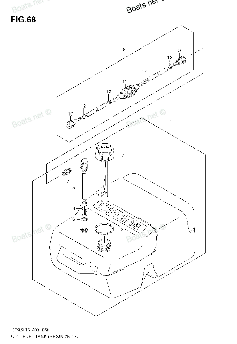
Number on catalog scheme: 8
Compatible models:
Suzuki entire parts catalog list:
- OPT:FUEL TANK (RESIN 25L) » 65700-87D17
- OPT:FUEL TANK (RESIN 25L) » 65700-87D17
- OPT:FUEL TANK (RESIN 25L) » 65700-87D17
- OPT:FUEL TANK (RESIN 25L) » 65700-87D17
- OPT:FUEL TANK (RESIN 25L) » 65700-87D17
- OPT:FUEL TANK (RESIN 25L) » 65700-87D17
- OPT:FUEL TANK (RESIN 25L) » 65700-87D17
- OPT:FUEL TANK (RESIN 25L) » 65700-87D17
- OPT:FUEL TANK (RESIN 25L) » 65700-87D17
- OPT:FUEL TANK (RESIN 25L) » 65700-87D17
- FUEL TANK » 65700-87D17
- FUEL TANK » 65700-87D17
- FUEL TANK (PLASTIC) » 65700-87D17
- FUEL TANK (STEEL) » 65700-87D17
- FUEL TANK » 65700-87D17
- FUEL TANK (PLASTIC,25L) » 65700-87D17
- FUEL TANK » 65700-87D17
- FUEL TANK (PLASTIC,25L) » 65700-87D17
- OPTIONAL : FUEL TANK (DT4:233284~) » 65700-87D17
- FUEL TANK (MODEL:88~92) » 65700-87D17
- FUEL TANK (MODEL:93~98-PLASTIC-25L) » 65700-87D17
- OPTIONAL : FUEL TANK (DT4:233284~) » 65700-87D17
Information:
Troubleshooting
Troubleshooting can be difficult. On the following pages is a list of possible problems. To make a repair to a problem, make reference to the cause and correction.This list of problems, causes and corrections, will only give an indication of where a possible problem can be, and what repairs are needed. Normally, more or other repair work is needed beyond the recommendation in the list.Remember that a problem is not normally caused only by one part, but by the relation of one part with other parts. This list cannot give all possible problems and corrections. The serviceman must find the problem and its source, then make the necessary repairs.1. Sending Unit For Water Temperature Activates At Wrong Temperature.2. Contactor Switch For Oil Pressure Does Not Activate Shutoff Solenoid.3. Sending Unit For Torque Converter Temperature Activates At Wrong Temperature.4. Sending Unit For Oil Pressure Activates At Wrong Temperature.Troubleshooting Problems
Problem 1: Sending Unit For Water Temperature Activates At Wrong Temperature. Probable Cause:1. Wrong Setting Of Sending Unit Make a test of temperature setting and if necessary install new contactor switch with correct setting. See Specifications. Problem 2: Contactor Switch For Oil Pressure Does Not Activate Shutoff Solenoid. Probable Cause:1. Wrong Connections Check connections, wiring and correct where necessary.2. Wrong Setting Of Switch Problem 3: Sending Unit For Torque Converter Temperature At Wrong Temperature. Probable Cause:1. Wrong Setting Of Sending Unit Make a test of temperature setting and if necessary install new contactor switch with correct setting. See Specifications. Problem 4: Sending Unit For Oil Pressure Activates at wrong temperature. Probable Cause:1. Wrong Setting Of Sending Unit Make a test of temperature setting and if necessary install new contactor switch with correct setting. See Specifications.Instruments And Gauges
Oil Pressure Switch
Oil Pressure Switch
Terminal 1 is common. Terminal 2 is normally open. Terminal 3 is normally closed. For the pressure at which each circuit will be switched find the switch in specifications section of this manual.1. Connect the oil pressure switch to a pressure source that can be measured with accuracy.2. Connect a circuit tester between terminal (2) and terminal (1).3. With pressure increase, the circuit light will light.4. With pressure decrease, the circuit light will go out.5. Connect a circuit tester between terminal (3) and terminal (1).6. With pressure increase, the circuit light will go out.7. With pressure decrease, the circuit light will light.8. If the switch fails to operate at the correct pressures, replace the switch.Oil Pressure Sending Unit
Oil Pressure Sending Unit
(1) Connection. (2) Fitting.1. Connect the sending unit to a pressure source that can be measured with accuracy.2. Connect the 6V7070 Digital Multimeter between fitting (2) and terminal (1).3. Refer to Oil Pressure Sending Unit in Specifications. Take resistance readings at the pressure shown in the chart. Tap sender when checking calibration. Take readings on decreasing pressure.4. If a unit does not have the correct resistance readings, replace the unit.Water Temperature Sending Unit
Heat Sink
[Dimensions in mm (inches)]1. Make a heat sink as shown. Material can be brass, steel or cast iron. Drill a 23/32 in hole through the plate and use a tap to make 1/2 in NPT threads.
Water Temperature Sending Unit
(1) Connection. (2) Nut. (3) Bulb.2. Install the water temperature sending unit in the heat sink.
Switch Test (Typical Example)
(4) 2F7112 Thermometer. (5) Fabricated heat sink.3. Put heat sink (5) and water temperature sending unit in water as shown. Use blocks to support the heat sink at surface level.4. Connect the 6V7070 Digital Multimeter between terminal (1) and nut (2). Do not let the bulb (3) have contact with the pan.5. Put a 2F7112 Thermometer (4) in the water to measure the temperature.6. Stir the water while using a torch to heat the water. Refer to Water Temperature Sending Unit in Specifications. Take resistance readings at the temperatures shown in the chart.7. If a unit does not have the correct resistance readings, replace the unit.Torque Converter Temperature Sending Unit
Torque Converter Temperature Sending Unit
(1) Connection. (2) Nut. (3) Bulb.1. Connect the 6V7070 Digital Multimeter between terminal (1) and nut (2). Put bulb (3) in heat sink then into a pan of water. Do not let the bulb have contact with the pan (see Water Temperature Sending Unit for more detail).2. Put a 2F7112 Thermometer in the water to measure the temperature.3. Refer to Torque Converter Temperature Sending Unit in Specifications. Take resistance readings at the temperature shown in the chart.4. If a unit does not have the correct resistance readings, replace the unit.
Parts clip Suzuki:
65781-98500
65781-98500 Clip
25ELT, 25ELX, 30ELE, 30ESE, 30MLE, DF100, DF100, DF115, DF115, DF115TL, DF140, DF140, DF140T, DF140T, DF140Z, DF140Z, DF140Z, DF140Z, DF15, DF15, DF15, DF15A, DF15S, DF20A, DF25, DF25(R)S, DF25Q, DF25Q(QR), DF25R, DF25R, DF25T, DF30, DF30Q, DF30Q(QR)
09401-08410

09401-08410 CLIP
DF4, DF4, DF46, DF4L, DF6, DF6, DF6L, DT150, DT150SSH, DT150SSJ, DT150SSK, DT150SSL, DT150SSM, DT150SSN, DT150STCLP, DT150STCLR, DT150STCLS, DT150STCLT, DT150TCLH, DT150TCLJ, DT150TCLK, DT150TCLL, DT150TCLM, DT150TCLN, DT150TCLP, DT150TCLR, DT150TCXG
15331-94300
15331-94300 Clip
DT20ELG, DT20ELH, DT20ELJ, DT20ESG, DT20ESH, DT20ESJ, DT20MLG, DT20MLH, DT20MLJ, DT20MSG, DT20MSH, DT20MSJ, DT25ELF, DT25ELG, DT25ELH, DT25ELJ, DT25ESG, DT25ESH, DT25ESJ, DT25MLD, DT25MLE, DT25MLF, DT25MLG, DT25MLH, DT25MLJ, DT25MSD, DT25MSE, DT25MSF
09401-11407
09401-11407 CLIP
DF100, DF100, DF115, DF115, DF115TL, DF140, DF140, DF140T, DF140T, DF140Z, DF140Z, DF140Z, DF140Z, DF150TX, DF150ZX, DF175TX, DF175ZX, DF25, DF25Q, DF25Q(QR), DF25T, DF30, DF30Q, DF30Q(QR), DF30T, DF40, DF40, DF40QH, DF40TL, DF50, DF50, DF50QH, DF50T
65700-87D32
65700-87D21
09401-05402
09401-05402 CLIP
DF15, DF15, DF15S, DF25(R)S, DF25R, DF9.9R, DF9.9RL, DF9.9S, DF9.9TH, DF9.9TH, DF99R, DF99TH
13494-94J00
13494-94J00 CLIP
DF15, DF15, DF15, DF15S, DF25(R)S, DF25R, DF25R, DF8A, DF8AR, DF9.9, DF9.9A, DF9.9AR, DF9.9R, DF9.9RL, DF9.9S, DF9.9TH, DF9.9TH, DF99AR, DF99R, DF99TH