09159-08018 Nut, Swivel Shaft Suzuki
DF2.5, DF2.5, DF2.5, DF2.5s, DF25, DT2.2SV, DT2B, DT2C, DT2D, DT2E, DT2F, DT2LG, DT2LH, DT2LJ, DT2LK, DT2LL, DT2N, DT2SG, DT2SH, DT2SJ, DT2SK, DT2SL, DT2SM, DT2SN, DT2SP, DT2SR, DT2SS, DT2ST, DT2T, DT2X, DT2Z, DT3.5LN, DT3.5LT, DT3.5LX, DT3.5LZ, DT3.
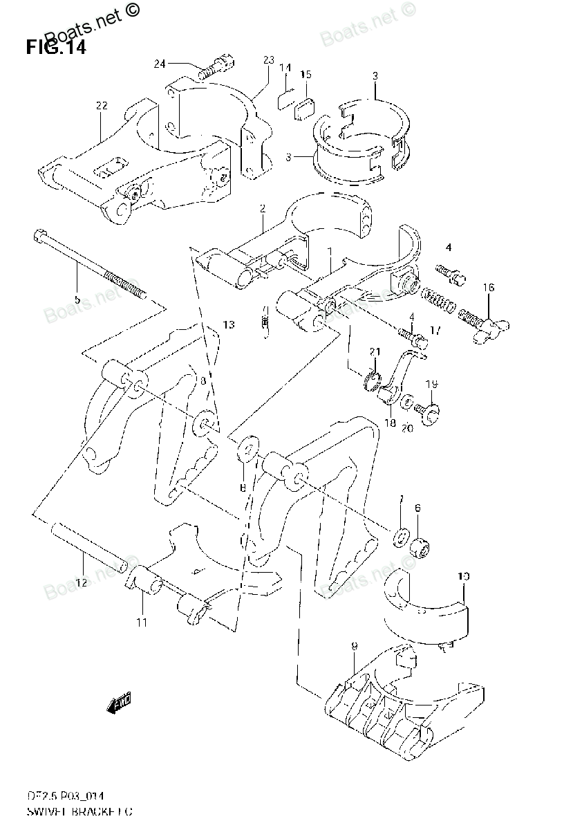
Nut

Price: query
Rating:
Number on catalog scheme: 6
Compatible models:
DF2.5
DF2.5s
DF25
DT2.2SV
DT2B
DT2C
DT2D
DT2E
DT2F
DT2LG
DT2LH
DT2LJ
DT2LK
DT2LL
DT2N
DT2SG
DT2SH
DT2SJ
DT2SK
DT2SL
DT2SM
DT2SN
DT2SP
DT2SR
DT2SS
DT2ST
DT2T
DT2X
DT2Z
DT3.5LN
DT3.5LT
DT3.5LX
DT3.5LZ
DT3.5SN
DT3.5ST
DT3.5SX
DT3.5SZ
DT4.5LB
DT4.5SB
DT4D
DT5LT
DT5LX
DT5ST
DT5SX
DT7.5LB
DT7.5LC
DT7.5LN
DT7.5SB
DT7.5SC
DT7.5SN
DT8LT
DT8LX
DT8ST
DT8SX
DT9C
DT9D
DT9F
Suzuki
Suzuki entire parts catalog list:
- SWIVEL BRACKET » 09159-08018
- SWIVEL BRACKET » 09159-08018
- SWIVEL BRACKET (210001~) » 09159-08018
- SWIVEL BRACKET (310001~) » 09159-08018
- SWIVEL BRACKET » 09159-08018
- SWIVEL BRACKET » 09159-08018
- CLAMP BRACKET » 09159-08018
- Clamp Bracket » 09159-08018
- Clamp Bracket » 09159-08018
- CLAMP BRACKET » 09159-08018
- CLAMP BRACKET » 09159-08018
- CLAMP BRACKET » 09159-08018
- CLAMP BRACKET » 09159-08018
- CLAMP BRACKET » 09159-08018
- CLAMP BRACKET » 09159-08018
- CLAMP BRACKET » 09159-08018
- CLAMP BRACKET » 09159-08018
- Clamp Bracket » 09159-08018
- CLAMP BRACKET » 09159-08018
- CLAMP BRACKET » 09159-08018
- CLAMP BRACKET » 09159-08018
- CLAMP BRACKET » 09159-08018
- CLAMP BRACKET » 09159-08018
- CLAMP BRACKET » 09159-08018
- CLAMP BRACKET » 09159-08018
- CLAMP BRACKET » 09159-08018
- CLAMP BRACKET » 09159-08018
- CLAMP BRACKET » 09159-08018
- CLAMP BRACKET » 09159-08018
- Clamp Bracket - Swivel Bracket 1 » 09159-08018
- Clamp Bracket - Swivel Bracket 1 » 09159-08018
- Clamp Bracket - Swivel Bracket 2 » 09159-08018
- Clamp Bracket » 09159-08018
- Clamp Bracket » 09159-08018
- Clamp Bracket » 09159-08018
- Clamp Bracket » 09159-08018
- Clamp Bracket » 09159-08018
- Clamp Bracket » 09159-08018
- Clamp Bracket » 09159-08018
- Clamp Bracket » 09159-08018
- Clamp Bracket » 09159-08018
- Clamp Bracket » 09159-08018
- Clamp Bracket » 09159-08018
- Clamp Bracket » 09159-08018
- Clamp Bracket » 09159-08018
- Clamp Bracket » 09159-08018
- Clamp Bracket » 09159-08018
- Clamp Bracket » 09159-08018
- Clamp Bracket » 09159-08018
- Clamp Bracket » 09159-08018
- Clamp Bracket » 09159-08018
- Clamp Bracket » 09159-08018
- Clamp Bracket » 09159-08018
- Clamp Bracket » 09159-08018
- Clamp Bracket » 09159-08018
- Clamp Bracket » 09159-08018
- Clamp Bracket » 09159-08018
- Clamp Bracket » 09159-08018
- Clamp Bracket » 09159-08018
- Clamp Bracket » 09159-08018
Information:
Illustration 1 g02478716
Drain the coolant from the cooling system into a suitable container for storage or disposal. Refer to Operation and Maintenance Manual, "Cooling System Coolant - Change" for the correct procedure.
Remove bolts (2) and bolt (9) from tube assembly (3).
Remove tube assembly (3) from the cylinder head and the exhaust cooler.
Remove gasket (1) (not shown) and gasket (10) (not shown) from tube assembly (3).
Prior to and during removal of bolts (6) and bolts (11) apply releasing fluid to the bolts. Remove bolts (6) and bolts (11) from tube assembly (8).
Remove tube assembly (8) from the exhaust cooler and the exhaust manifold.
Remove gasket (7) (not shown) and gasket (12) (not shown) from tube assembly (8).
Remove bolt (5) and bolt (13) from dipstick tube assembly (4).
Loosen nut (14) on dipstick tube assembly (4). Remove the dipstick tube assembly.
Remove O-ring seal (15) (not shown) and seal (16) (not shown) from the dipstick tube assembly.
Illustration 2 g02477641
Tighten sequence of exhaust manifold
Illustration 3 g02478717
Loosen bolts (15) in reverse numerical order. Refer to Illustration 2. Note: Loosen the bolts in reverse numerical order will help prevent distortion of the exhaust manifold.
Remove bolts (15) and spacers (16) from exhaust manifold (17). Note position of the different length spacer. Note: Support the manifold as the bolts are removed.
Remove exhaust manifold (17).
Remove exhaust manifold gasket (18) (not shown). Installation Procedure
Table 1
Required Tools
Tool Part Number Part Description Qty
A 366-1820 Manifold Alignment Pins 2
B 377-2038 Manifold Alignment Pins 1
C(1) - Loctite 575 1
(2)D - Loctite 565 1
(1) If Loctite 575 is not available, install new bolts
(2) If Loctite 565 is not available, install new bolts
Ensure that the exhaust manifold is clean and free from damage. If necessary, replace the exhaust manifold. Clean the gasket surface of the cylinder head.
Illustration 4 g02477697
Tighten sequence of exhaust manifold and Tooling position
Illustration 5 g02478717
Position a new exhaust manifold gasket (18) (not shown) onto the cylinder head. Install Tooling (A) in Positions (X) and Tooling (B) in Positions (Y). Refer to Illustration 4. Note: Ensure that the exhaust manifold gasket is correctly oriented.
Align exhaust manifold (17) with Tooling (A) and Tooling (B). Install the exhaust manifold to the cylinder head.
If bolts (15) have been previously used, thoroughly clean the bolts. Tooling (C) or Tooling (D) should be applied to the first two threads of the bolts. If Tooling (C) or Tooling (D) is not available, new bolts should be installed. Note: Do not apply Tooling (C) or Tooling (C) to new bolts.
Install bolts (15) and spacers (16) hand tight. Ensure that the different length spacer is installed into the correct position.
Remove Tooling (A) and Tooling (B). Install remaining bolts (15) and spacers (16) hand tight.
Tighten bolts (15) to a torque of 44 N m (32 lb ft). Tighten the bolts in the sequence that is shown in Illustration 4.
Illustration 6 g02478716
Ensure that all tube assemblies are free from restriction and damage.
Position a new gasket (7) (not shown) and a gasket (12) (not shown) onto tube assembly (8).
Install tube assembly (8) onto the exhaust cooler and the exhaust manifold.
Install bolts (6) and bolts (11) to tube assembly (8). Tighten the bolts to a torque of 22 N m (195 lb in).
Position a new gasket (1) (not shown) a new gasket (10) (not shown) onto tube assembly (3).
Install tube assembly (3) onto the cylinder head and the exhaust cooler.
Install bolts (2) and bolt (9) to tube assembly (3).
Tighten bolt (9) to a torque of 18 N m (159 lb in). Tighten bolts (2) to a torque of 22 N m (195 lb in).
Install a new O-ring seal (15) (not shown) and a new seal (16) (not shown) to the dipstick tube assembly. Loosely install nut (14) for dipstick tube assembly (4).
Install bolt (5) and bolt (13) to dipstick tube assembly (4).
Tighten nut (14) to a torque of 18 N m (159 lb in). Tighten bolts (5) and bolt (13) to a torque of 22 N m (195 lb in).
Fill the cooling system with coolant. Refer to Operation and Maintenance Manual, "Cooling System Coolant - Change" for the correct procedure. End By:
Install turb
Parts nut Suzuki:
13567-98411
13567-98410
08310-22108
08310-22108 Nut, Fuel Connector
20ELB, 20ELC, 20ELN, 25ELB, 25ELC, 25ELN, 25ELT, 25ELX, 30ELE, 30ESE, 30MLE, DT14C, DT14D, DT14F, DT15 MLE, DT15ELD, DT15ELE, DT15ELF, DT15ESD, DT15ESE, DT15ESF, DT15MLD, DT15MLF, DT15MSD, DT15MSE, DT15MSF, DT16LB, DT16LC, DT16LN, DT16LT, DT16LT, DT1
08310-12088
08310-12088 Nut
DT5LD, DT5LT, DT5LX, DT5LZ, DT5SD, DT5ST, DT5SX, DT5SZ, DT6LE, DT6LF, DT6SE, DT6SF, DT7.5LB, DT7.5LC, DT7.5LN, DT7.5SB, DT7.5SC, DT7.5SN, DT8LD, DT8LE, DT8LF, DT8LT, DT8LX, DT8LZ, DT8SD, DT8SE, DT8SF, DT8ST, DT8SX, DT8SZ, DT9C, DT9D, DT9F
58131-93000
58131-93000 Nut, Propeller
20ELB, 20ELC, 20ELN, 25ELB, 25ELC, 25ELN, 25ELT, 25ELX, DT14C, DT14D, DT14F, DT16LB, DT16LC, DT16LN, DT16SB, DT16SC, DT16SN, DT20ESB, DT20ESC, DT20ESN, DT20MLB, DT20MLC, DT20MLN, DT20MSB, DT20MSC, DT20MSN, DT25ELZ, DT25ESB, DT25ESC, DT25ESN, DT25EST,
08310-22088

08310-22088 Nut
20ELB, 20ELC, 20ELN, 25ELB, 25ELC, 25ELN, 25ELT, 25ELX, 30ELE, 30ESE, 30MLE, DT15 MLE, DT15ELD, DT15ELE, DT15ELF, DT15ESD, DT15ESE, DT15ESF, DT15MLD, DT15MLF, DT15MSD, DT15MSE, DT15MSF, DT16LT, DT16LT, DT16LT, DT16ST, DT16ST, DT16ST, DT20ESB, DT20ESC
08310-11108
08310-00067

08310-00067 NUT
DF100, DF100, DF100, DF100A, DF115, DF115, DF115, DF115A, DF115TL, DF140, DF140, DF140, DF140A, DF140T, DF140T, DF140Z, DF140Z, DF140Z, DF140Z, DF15, DF15, DF150, DF150, DF150, DF150TX, DF150ZX, DF15S, DF175, DF175, DF175, DF175TX, DF175ZX, DF2.5, DF