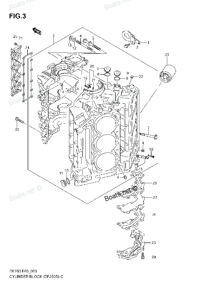
09159-10116 NUT, CRANKCASE Suzuki
DF200, DF200, DF200, DF225, DF225, DF225, DF250, DF250, DF250, DF250A, DF300, DF300, DF300A
NUT

Price: query
Number on catalog scheme: 12
Suzuki entire parts catalog list:
- CYLINDER BLOCK (DF250S) » 09159-10116
- CYLINDER BLOCK (DF250S) » 09159-10116
- CYLINDER BLOCK (DF250ST) » 09159-10116
- CYLINDER BLOCK (DF250S) » 09159-10116
- CYLINDER BLOCK (DF250S) » 09159-10116
- CYLINDER BLOCK (DF250ST) » 09159-10116
- CYLINDER BLOCK (DF250S) » 09159-10116
- CYLINDER BLOCK (DF250S) » 09159-10116
- CYLINDER BLOCK (DF250ST) » 09159-10116
- CYLINDER BLOCK » 09159-10116
- CYLINDER BLOCK » 09159-10116
- CYLINDER BLOCK » 09159-10116
- CYLINDER BLOCK (210001~) » 09159-10116
- CYLINDER BLOCK (310001~) » 09159-10116
Information:
The aftertreatment identification module communicates with the engine ECM to ensure that the correct Integrated Clean Emissions Module (IGCEM) is installed.If the total operating hours of the engine are greater than 100, the aftertreatment identification module will cease to send the signal. The diagnostic codes that are listed in Table 1 will be disabled.
Illustration 1 g06142837
Schematic for the aftertreatment identification module
Illustration 2 g02174636
View of the pin locations on the 31-pin connector and the 40-pin connector for the aftertreatment identification module
Illustration 3 g02013237
View of the pin locations on the P2 connector for the aftertreatment identification module
(18) Aftertreatment identification module signal
(36) Aftertreatment identification module return
(45) CEM 5 VDC supply
Illustration 4 g02084579
Typical example of the connector for the aftertreatment identification module
(1) 5 VDC Supply
(3) Signal
(6) GroundComplete the procedure in the order in which the steps are listed.
Table 2
Troubleshooting Test Steps Values Results
1. Check for Diagnostic Codes
A. Establish communication between the electronic service tool and the Dosing Control Unit (DCU) . Refer to Troubleshooting, "Electronic Service Tools", if necessary.
B. Turn the keyswitch to the ON position.
C. Look for "-2", "-8", or "-14" active or logged codes.
Diagnostic code
Result: A 5576-2 (3468-2) or 5576-14 (3468-14) diagnostic code is active.
Proceed to Test Step 9.
Result: A 5576-8 (3468-8) diagnostic code is active.
Proceed to Test Step 2.
2. Inspect Electrical Connectors and Wiring
A. Inspect the P2/J2 connector. Refer to Troubleshooting, "Electrical Connectors - Inspect" for details.
B. Inspect the 31-pin connector and the 40-pin connector. Refer to Troubleshooting, "Electrical Connectors - Inspect" for details.
C. Inspect the connector for the aftertreatment identification module. Refer to Troubleshooting, "Electrical Connectors - Inspect" for details.
D. Perform a 45 N (10 lb) pull test on each of the wires in the ECM connector that are associated with the aftertreatment identification module.
E. Check the screw for the ECM connector for the correct torque of 6 N m (53 lb in).
F. Check the harness for abrasion and pinch points from the aftertreatment identification module back to the ECM.
Connectors and wiring
Result: There is a fault with the harness or the connectors.
Repair: Repair the connectors or the harness and/or replace the connectors or the harness. Ensure that all the seals are correctly in place and ensure that the connectors are correctly connected.
Use the electronic service tool to clear all logged diagnostic codes and then verify that the repair has eliminated the fault.
Result: All connectors, pins, and sockets are correctly coupled and/or inserted. The harness is free of corrosion, abrasion, and pinch points.
Proceed to Test Step 3.
3. Measure the Voltage to the Aftertreatment Identification Module
A. Turn the keyswitch to the OFF position.
B. Disconnect the aftertreatment identification module from the harness.
C. Turn the keyswitch to the ON position.
D. Measure the voltage at the harness connector for the aftertreatment identification module from terminal 1 to terminal 6.
4.84 to 5.16 VDC.
Result: The supply voltage is out of the nominal range.
Proceed to Test Step 4.
Result: The supply voltage is correct.
Proceed to Test Step 6.
4. Measure the Voltage to the 40-Pin Connector
A. Turn the keyswitch to the OFF position.
B. Disconnect the 40-pin connector.
C. Turn the keyswitch to the ON position.
D. Measure the voltage at the 40-pin connector on the harness between the engine and the CEM from pin 1 to pin 28.
4.84 to 5.16 VDC
Result: The voltage is within the expected range. The fault is in the harness.
Repair: Repair the faulty wiring or replace the faulty wiring.
Use the electronic service tool to verify that the repair eliminates the fault.
Result: The voltage is out of the expected range.
Reconnect the 40-pin connector. Proceed to Test Step 5.
5. Measure the Voltage to the 31-Pin Connector
A. Turn the keyswitch to the OFF position.
B. Disconnect the 31-pin connector.
C. Turn the keyswitch to the ON position.
D. Measure the voltage at the 31-pin connector on the engine harness from pin 1 to pin 28.
4.84 to 5.16 VDC
Result: The voltage is within the expected range. The fault is in the harness between the 31-pin connector and the 40-pin connector.
Repair: Repair the faulty wiring or r
Parts nut Suzuki:
08316-10087

08316-10087 NUT
DF100, DF100, DF100, DF100A, DF115, DF115, DF115, DF115A, DF115TL, DF140, DF140, DF140, DF140A, DF140T, DF140T, DF140Z, DF140Z, DF140Z, DF140Z, DF15, DF15, DF15, DF150, DF150, DF150, DF150TX, DF150ZX, DF15A, DF15S, DF175, DF175, DF175, DF175TX, DF175
09159-22006

09159-22006 NUT
DF100, DF100, DF100, DF100A, DF115, DF115, DF115, DF115A, DF115TL, DF140, DF140, DF140, DF140A, DF140T, DF140T, DF140Z, DF140Z, DF140Z, DF140Z, DF15, DF15, DF15, DF150, DF150, DF150, DF150TX, DF150ZX, DF15S, DF175, DF175, DF175, DF175TX, DF175ZX, DF2
08310-00067

08310-00067 NUT
DF100, DF100, DF100, DF100A, DF115, DF115, DF115, DF115A, DF115TL, DF140, DF140, DF140, DF140A, DF140T, DF140T, DF140Z, DF140Z, DF140Z, DF140Z, DF15, DF15, DF150, DF150, DF150, DF150TX, DF150ZX, DF15S, DF175, DF175, DF175, DF175TX, DF175ZX, DF2.5, DF
09141-18005

09141-18005 NUT
DF100, DF100, DF100, DF100A, DF115, DF115, DF115, DF115A, DF115TL, DF140, DF140, DF140, DF140A, DF140T, DF140T, DF140Z, DF140Z, DF140Z, DF140Z, DF150, DF150, DF150, DF150TX, DF150ZX, DF175, DF175, DF175, DF175TX, DF175ZX, DF200, DF200, DF200, DF200T,
09140-16026

09140-16026 NUT
DF200, DF200, DF200, DF225, DF225, DF225, DF250, DF250, DF250, DF250A, DF300, DF300, DF300A, DT150, DT150SSH, DT150SSJ, DT150SSK, DT150SSL, DT150SSM, DT150SSN, DT150STCLP, DT150STCLR, DT150STCLS, DT150STCLT, DT150TCLH, DT150TCLJ, DT150TCLK, DT150TCLL
67471-99E00
67471-99E00 NUT, CLUTCH LEVER
DF25, DF250A, DF25Q, DF25Q(QR), DF25T, DF30, DF300, DF300, DF300A, DF30Q, DF30Q(QR), DF30T, DF40, DF40, DF40QH, DF40TL, DF50, DF50, DF50QH, DF50TL, DF60, DF60HL, DF60TL, DF70, DF70THL, DF70TL, DT150, DT200, DT225
34300-98J10
34300-98J10 NUT
DF100, DF100, DF100, DF115, DF115, DF115, DF140, DF140, DF140, DF140T, DF140T, DF140Z, DF140Z, DF140Z, DF140Z, DF150, DF150, DF150, DF175, DF175, DF175, DF200, DF200, DF225, DF225, DF250, DF250, DF300, DF300, DF40, DF40, DF50, DF50, DF60, DF70, DF70A
34815-98J00
34815-98J00 NUT
DF100, DF100, DF100, DF115, DF115, DF115, DF140, DF140, DF140, DF140T, DF140T, DF140Z, DF140Z, DF140Z, DF140Z, DF150, DF150, DF150, DF175, DF175, DF175, DF200, DF200, DF225, DF225, DF250, DF250, DF300, DF300, DF40, DF40, DF50, DF50, DF60, DF70, DF70A