65890-95D00 OUTLET ASSY Suzuki
DF15, DF15, DF15S, DF25, DF25(R)S, DF25Q, DF25Q(QR), DF25R, DF25R, DF25T, DF30, DF30Q, DF30Q(QR), DF30T, DF40, DF40, DF40QH, DF40TL, DF50, DF50, DF50QH, DF50TL, DF8AR, DF9.9AR, DF9.9R, DF9.9RL, DF9.9S, DF9.9TH, DF9.9TH, DF99AR, DF99R, DF99TH, DT15C,
OUTLET

Price: query
Rating:
You can buy parts:
As an associate, we earn commssions on qualifying purchases through the links below

$15.48
06-09-2023
70.0 Grams
-: -
Boat Motor 65890-99100 Outlet Fuel Tank Pick up Assy 65890-95D00 65890-950D1 for Suzuki Outboard DT DF 4HP - 225HP 2/4 Stroke Motor Engine
100% Aftermarket Made in Taiwan Quality || For Suzuki Outboard part number: 65890-99100, 65890-95D00, 65890-950D1 (IMPT: check OEM part number before purchase!!) || For Suzuki Outboard DT DF 4HP - 40HP (2/4 Stroke) engine || OUTLET PICK UP BODY (FUEL TANK) || For Boat Motor Suzuki Outboard Fuel Tank
100% Aftermarket Made in Taiwan Quality || For Suzuki Outboard part number: 65890-99100, 65890-95D00, 65890-950D1 (IMPT: check OEM part number before purchase!!) || For Suzuki Outboard DT DF 4HP - 40HP (2/4 Stroke) engine || OUTLET PICK UP BODY (FUEL TANK) || For Boat Motor Suzuki Outboard Fuel Tank
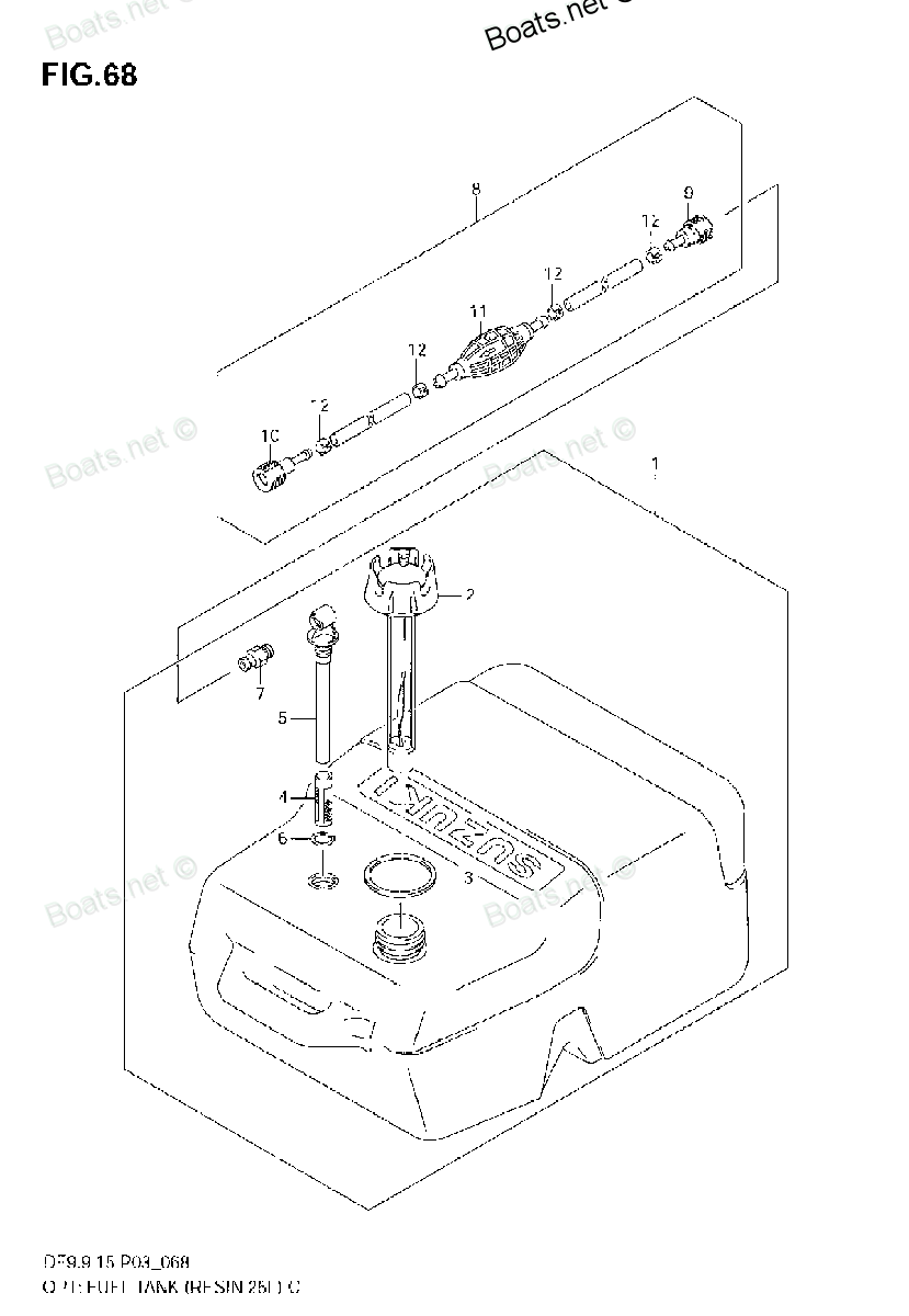
Number on catalog scheme: 5
Compatible models:
DF15
DF15S
DF25
DF25(R)S
DF25Q
DF25Q(QR)
DF25R
DF25T
DF30
DF30Q
DF30Q(QR)
DF30T
DF40
DF40QH
DF40TL
DF50
DF50QH
DF50TL
DF8AR
DF9.9AR
DF9.9R
DF9.9RL
DF9.9S
DF9.9TH
DF99AR
DF99R
DF99TH
DT15C
DT25C
DT30C
DT30CRLJ
DT30CRSJ
DT30MCLJ
DT30MCSJ
DT40C
DT9.9 CELK
DT9.9CELJ
DT9.9CELL
DT9.9CELM
DT9.9CELN
DT9.9CELP
DT9.9CELR
DT9.9CELS
DT9.9CELT
DT9.9CENK
DT9.9CESJ
DT9.9CESK
DT9.9CESL
DT9.9CESM
DT9.9CESN
DT9.9CESP
DT9.9CESR
DT9.9CESS
DT9.9CEST
DT9.9CNELP
DT9.9CNELR
DT9.9CNELS
DT9.9CNELT
DT9.9CNEXP
DT9.9CNEXR
DT9.9CNEXS
DT9.9CNEXT
DT9.9CNEXV
DT9.9CNJ
DT9.9CNK
DT9.9CNL
DT9.9CNLN
DT9.9MCLJ
DT9.9MCLK
DT9.9MCLL
DT9.9MCLM
DT9.9MCLN
DT9.9MCLP
DT9.9MCLR
DT9.9MCLS
DT9.9MCLT
DT9.9MCLV
DT9.9MCNLR
DT9.9MCNLT
DT9.9MCNLV
DT9.9MCSJ
DT9.9MCSK
DT9.9MCSL
DT9.9MCSM
DT9.9MCSN
DT9.9MCSP
DT9.9MCSR
DT9.9MCSS
DT9.9MCST
DT9.9MCSV
Suzuki
Suzuki entire parts catalog list:
- OPT:FUEL TANK (RESIN 25L) » 65890-95D00
- OPT:FUEL TANK (RESIN 25L) » 65890-95D00
- OPT:FUEL TANK (RESIN 25L) » 65890-95D00
- FUEL TANK (RESIN) » 65890-95D00
- FUEL TANK (RESIN) » 65890-95D00
- FUEL TANK (RESIN) » 65890-95D00
- FUEL TANK (RESIN) » 65890-95D00
- FUEL TANK (RESIN) » 65890-95D00
- FUEL TANK (RESIN) » 65890-95D00
- FUEL TANK (RESIN) » 65890-95D00
- FUEL TANK (RESIN) » 65890-95D00
- FUEL TANK (RESIN) » 65890-95D00
- FUEL TANK (RESIN) » 65890-95D00
- FUEL TANK (RESIN) » 65890-95D00
- FUEL TANK (PLASTIC) » 65890-95D00
- FUEL TANK (PLASTIC) » 65890-95D00
- FUEL TANK (PLASTIC) » 65890-95D00
- FUEL TANK (PLASTIC) » 65890-95D00
- FUEL TANK (PLASTIC) » 65890-95D00
- FUEL TANK (PLASTIC) » 65890-95D00
- FUEL TANK (PLASTIC) » 65890-95D00
- FUEL TANK (PLASTIC) » 65890-95D00
- OPT:FUEL TANK (RESIN 25L) » 65890-95D00
- OPT:FUEL TANK (RESIN 25L) » 65890-95D00
- OPT:FUEL TANK (RESIN 25L) » 65890-95D00
- OPT:FUEL TANK (RESIN 25L) » 65890-95D00
- OPT:FUEL TANK (RESIN 25L) » 65890-95D00
- OPT:FUEL TANK (RESIN 25L) » 65890-95D00
- OPT:FUEL TANK (RESIN 25L) » 65890-95D00
- OPT:FUEL TANK (RESIN 25L) » 65890-95D00
- OPT:FUEL TANK (RESIN 25L) » 65890-95D00
- OPT:FUEL TANK (RESIN 25L) » 65890-95D00
- FUEL TANK (PLASTIC) » 65890-95D00
- FUEL TANK (PLASTIC,25L) » 65890-95D00
- FUEL TANK (PLASTIC,25L) » 65890-95D00
- FUEL TANK » 65890-95D00
- FUEL TANK » 65890-95D00
- FUEL TANK » 65890-95D00
- FUEL TANK » 65890-95D00
- FUEL TANK (MODEL:93~98-PLASTIC-25L) » 65890-95D00
- PLASTIC FUEL TANK » 65890-95D00
- PLASTIC FUEL TANK » 65890-95D00
- PLASTIC FUEL TANK » 65890-95D00
- PLASTIC FUEL TANK » 65890-95D00
- PLASTIC FUEL TANK » 65890-95D00
- PLASTIC FUEL TANK » 65890-95D00
- PLASTIC FUEL TANK » 65890-95D00
- PLASTIC FUEL TANK » 65890-95D00
- PLASTIC FUEL TANK » 65890-95D00
- PLASTIC FUEL TANK » 65890-95D00
- PLASTIC FUEL TANK » 65890-95D00
- PLASTIC FUEL TANK » 65890-95D00
- PLASTIC FUEL TANK » 65890-95D00
- PLASTIC FUEL TANK » 65890-95D00
- PLASTIC FUEL TANK » 65890-95D00
- PLASTIC FUEL TANK » 65890-95D00
- PLASTIC FUEL TANK » 65890-95D00
- PLASTIC FUEL TANK » 65890-95D00
- PLASTIC FUEL TANK » 65890-95D00
- PLASTIC FUEL TANK » 65890-95D00
- PLASTIC FUEL TANK » 65890-95D00
- PLASTIC FUEL TANK » 65890-95D00
- PLASTIC FUEL TANK » 65890-95D00
- PLASTIC FUEL TANK » 65890-95D00
- PLASTIC FUEL TANK » 65890-95D00
- PLASTIC FUEL TANK » 65890-95D00
- PLASTIC FUEL TANK » 65890-95D00
- PLASTIC FUEL TANK » 65890-95D00
- PLASTIC FUEL TANK » 65890-95D00
- PLASTIC FUEL TANK » 65890-95D00
- PLASTIC FUEL TANK » 65890-95D00
- PLASTIC FUEL TANK » 65890-95D00
- PLASTIC FUEL TANK » 65890-95D00
- PLASTIC FUEL TANK » 65890-95D00
- PLASTIC FUEL TANK » 65890-95D00
- PLASTIC FUEL TANK » 65890-95D00
- PLASTIC FUEL TANK » 65890-95D00
- PLASTIC FUEL TANK » 65890-95D00
- PLASTIC FUEL TANK » 65890-95D00
- PLASTIC FUEL TANK » 65890-95D00
- PLASTIC FUEL TANK » 65890-95D00
- PLASTIC FUEL TANK » 65890-95D00
- PLASTIC FUEL TANK » 65890-95D00
- PLASTIC FUEL TANK » 65890-95D00
- PLASTIC FUEL TANK » 65890-95D00
- PLASTIC FUEL TANK » 65890-95D00
- PLASTIC FUEL TANK » 65890-95D00
- PLASTIC FUEL TANK » 65890-95D00
- PLASTIC FUEL TANK » 65890-95D00
- PLASTIC FUEL TANK » 65890-95D00
- PLASTIC FUEL TANK » 65890-95D00
- PLASTIC FUEL TANK » 65890-95D00
- PLASTIC FUEL TANK » 65890-95D00
- PLASTIC FUEL TANK » 65890-95D00
- PLASTIC FUEL TANK » 65890-95D00
Information:
Engine Design
Cylinder and Valve LocationBore ... 137 mm (5.4 in)Stroke ... 165 mm (6.5 in)Displacement ... 14.6 liter (893 cu in)Number and Arrangement of Cylinders ... 6, InlineFiring Order (Injection Sequence) ... 1,5,3,6,2,4Valve lash setting with engine cold and stopped:Inlet ... 0.38 mm (.015 in)Exhaust ... 0.76 mm (.030 in)Rotation of Crankshaft (when viewed from flywheel end) ... CounterclockwiseRotation of Fuel Pump Camshaft (when viewed from pump drive end) ... Counterclockwise Front end of engine is opposite to flywheel end.Left side and right side of engine are as viewed from flywheel end.No. 1 cylinder is the front cylinder.Fuel System
Fuel Flow
Fuel System Schematic(1) Fuel injection nozzle.(2) Fuel injection lines.(3) Fuel return line.(4) Constant bleed orifice (part of elbow).(5) Fuel injection pump housing.(6) Fuel priming pump.(7) Check valves.(8) Fuel transfer pump.(9) Fuel tank.(10) Primary fuel filter.(11) Secondary fuel filter.Fuel is pulled from fuel tank (9) through primary fuel filter (10) by fuel transfer pump (8). From the fuel transfer pump the fuel is pushed through secondary fuel filter (11), and to the fuel manifold in fuel injection pump housing (5). Fuel pressure in the fuel manifold is determined by the fuel transfer pump spring. A constant bleed orifice is in the fuel return line elbow. Constant bleed orifice (4) lets a constant flow of fuel go through fuel return line (3) back to fuel tank (9). This helps keep the fuel cool and free from air. The individual fuel injection pumps get fuel from the fuel manifold and push fuel at a very high pressure through fuel injection lines (2) to fuel injection nozzles (1). Each fuel injection nozzle has very small holes in the tip that change the flow of fuel to a very fine spray that gives good fuel combustion in the cylinder.Fuel Injection Pump
The fuel injection pump increases the pressure of the fuel and sends an exact amount of fuel to the fuel injection nozzle. There is one fuel injection pump for each cylinder in the engine.
Fuel Injection Pump(1) Spill port.(2) Check valve.(3) Pump barrel.(4) Bypass port.(5) Pump plunger.(6) Spring.(7) Fuel rack.(8) Gear.(9) Lifter.(10) Cam.The fuel injection pump is moved by cam (10) of the fuel pump camshaft. When the camshaft turns, the cam raises lifter (9) and pump plunger (5). The pump plunger always makes a full stroke. As the camshaft turns farther, spring (6) returns the pump plunger and lifter to the bottom of the stroke.
Pump Barrel and Plunger Assembly(1) Spill port.(2) Check valve.(3) Pump barrel.(4) Bypass port.(5) Pump plunger.(11) Orifice reverse flow check valve.(12) Spring.(13) Spring.(14) Scroll.(15) Slot.When the pump plunger is at the bottom of the stroke, fuel at transfer pump pressure flows through spill port (1) and bypass port (4). Fuel fills pump barrel (3) in the area above pump plunger (5).
Pump Barrel and Plunger Assembly(1) Spill port.(2) Check valve.(3) Pump barrel.(4) Bypass port.(5) Pump plunger.(11) Orifice reverse flow check valve.(12) Spring.(13) Spring.(14) Scroll.(15) Slot.After pump plunger (5) begins the up stroke, fuel will be pushed out bypass port (4) until the top of the pump plunger closes the port. As the pump plunger travels farther up, the pressure of the fuel increases. At approximately 690 kPa (100 psi), check valve (2) opens and lets fuel flow into the fuel injection line to the fuel injection nozzle.
Pump Barrel and Plunger Assembly(1) Spill port.(2) Check valve.(3) Pump barrel.(4) Bypass port.(5) Pump plunger.(11) Orifice reverse flow check valve.(12) Spring.(13) Spring.(14) Scroll.(15) Slot.When the pump plunger travels farther up, scroll (14) uncovers spill port (1). The fuel above the pump plunger goes through slot (15), along the edge of scroll (14) and out spill port (1) back to the fuel manifold. This is the end of the injection stroke. The pump plunger can have more travel up, but no more fuel will be sent the fuel injection nozzle.
Pump Barrel and Plunger Assembly(1) Spill port.(2) Check valve.(4) Bypass port.(5) Pump plunger.(11) Orifice reverse flow check valve.(12) Spring.(13) Spring.(14) Scroll.(15) Slot.When spill port (1) is opened by plunger (5) the fuel nozzle closes and spring (13) closes check valve (2) as the pressure above plunger (5) drops below 690 kPa (100 psi). At the same time the orificed reverse flow check valve (11) opens.Orificed reverse flow check valve (11) closes when the fuel pressure in the fuel injection lines is 6900 kPa (1000 psi). This keeps the fuel in the injection line and above the reverse flow check valve at 6900 kPa (1000 psi). Orificed reverse flow check valve (11) prevents rough idle by stopping any secondary injection of fuel between injection strokes. This valve is only effective below 8250 kPa (1200 psi) and has no effect above that pressure. When the engine is shutdown, the pressure is gradually released through a small groove on the bottom face of orificed reverse flow check valve (11).When the pump plunger travels down and uncovers bypass port (4), fuel begins to fill the area above the pump plunger again, and the pump is ready to begin another stroke.The amount of fuel the fuel injection pump sends to the fuel injection nozzle on each pump stroke can be changed by the rotation of the pump plunger. Gear (8) is attached to the pump plunger and is in mesh with fuel rack (7). The governor moves the fuel rack which turns the fuel pump plungers according to the fuel needs of the engine. When the governor turns the pump plunger, scroll (14) on the plunger changes the distance between the top of pump plunger and the point where scroll (14) uncovers spill port (1). The longer the distance from the top of the pump plunger to the point where scroll (14) uncovers spill port (1), the more fuel will be injected.To stop the engine, the pump plunger is rotated so that slot (15) on the pump plunger is in line with spill port (1). The fuel will now go out the spill port and not to the fuel injection nozzle.Fuel Injection Nozzle
The fuel injection nozzle is installed in an adapter in the
Parts outlet Suzuki:
65890-99100

65890-99100 OUTLET ASSY
DF15, DF15, DF15S, DF4, DF4, DF46, DF4L, DF6, DF6, DF6L, DF8AR, DF9.9AR, DF9.9R, DF9.9RL, DF9.9S, DF9.9TH, DF9.9TH, DF99AR, DF99R, DF99TH, DT4, DT5Y, DT5Y, DT6, DT8CENK, DT8CENL, DT8CLJ, DT8CLK, DT8CLL, DT8CLM, DT8CNK, DT8CNL, DT8CSJ, DT8CSL, DT8CSM,