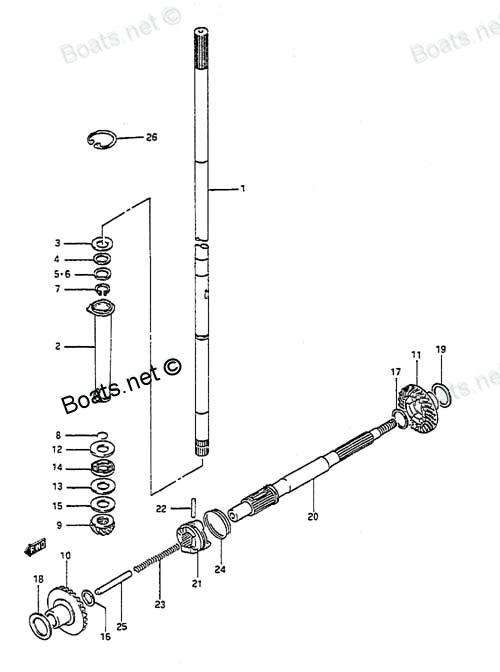
09160-16036 REVERSE PROP SHAFT WASHER Suzuki
DT8CENK, DT8CENL, DT8CLJ, DT8CLK, DT8CLL, DT8CLM, DT8CNK, DT8CNL, DT8CSJ, DT8CSL, DT8CSM, DT8MCLN, DT8MCLP, DT8MCLS, DT8MCLT, DT8MCLV, DT8MCSN, DT8MCSP, DT8MCSR, DT8MCSS, DT8MCST, DT8MCSV, DT8MSLR, DT8SCK, DT9.9 CELK, DT9.9CELJ, DT9.9CELL, DT9.9CELM,
REVERSE

Price: query
Rating:
Number on catalog scheme: 17
Compatible models:
DT8CENK
DT8CENL
DT8CLJ
DT8CLK
DT8CLL
DT8CLM
DT8CNK
DT8CNL
DT8CSJ
DT8CSL
DT8CSM
DT8MCLN
DT8MCLP
DT8MCLS
DT8MCLT
DT8MCLV
DT8MCSN
DT8MCSP
DT8MCSR
DT8MCSS
DT8MCST
DT8MCSV
DT8MSLR
DT8SCK
DT9.9 CELK
DT9.9CELJ
DT9.9CELL
DT9.9CELM
DT9.9CELN
DT9.9CELP
DT9.9CELR
DT9.9CELS
DT9.9CELT
DT9.9CENK
DT9.9CESJ
DT9.9CESK
DT9.9CESL
DT9.9CESM
DT9.9CESN
DT9.9CESP
DT9.9CESR
DT9.9CESS
DT9.9CEST
DT9.9CNELP
DT9.9CNELR
DT9.9CNELS
DT9.9CNELT
DT9.9CNEXP
DT9.9CNEXR
DT9.9CNEXS
DT9.9CNEXT
DT9.9CNEXV
DT9.9CNJ
DT9.9CNK
DT9.9CNL
DT9.9CNLN
DT9.9MCLJ
DT9.9MCLK
DT9.9MCLL
DT9.9MCLM
DT9.9MCLN
DT9.9MCLP
DT9.9MCLR
DT9.9MCLS
DT9.9MCLT
DT9.9MCLV
DT9.9MCNLR
DT9.9MCNLT
DT9.9MCNLV
DT9.9MCSJ
DT9.9MCSK
DT9.9MCSL
DT9.9MCSM
DT9.9MCSN
DT9.9MCSP
DT9.9MCSR
DT9.9MCSS
DT9.9MCST
DT9.9MCSV
Suzuki
Suzuki entire parts catalog list:
- TRANSMISSION » 09160-16036
- TRANSMISSION » 09160-16036
- TRANSMISSION » 09160-16036
- TRANSMISSION » 09160-16036
- TRANSMISSION » 09160-16036
- TRANSMISSION » 09160-16036
- TRANSMISSION » 09160-16036
- TRANSMISSION » 09160-16036
- TRANSMISSION » 09160-16036
- TRANSMISSION » 09160-16036
- TRANSMISSION » 09160-16036
- TRANSMISSION » 09160-16036
- TRANSMISSION » 09160-16036
- TRANSMISSION » 09160-16036
- TRANSMISSION » 09160-16036
- TRANSMISSION » 09160-16036
- TRANSMISSION » 09160-16036
- TRANSMISSION » 09160-16036
- TRANSMISSION » 09160-16036
- TRANSMISSION » 09160-16036
- TRANSMISSION » 09160-16036
- TRANSMISSION » 09160-16036
- TRANSMISSION » 09160-16036
- TRANSMISSION » 09160-16036
- TRANSMISSION » 09160-16036
- TRANSMISSION » 09160-16036
- TRANSMISSION » 09160-16036
- TRANSMISSION » 09160-16036
- TRANSMISSION » 09160-16036
- TRANSMISSION » 09160-16036
- TRANSMISSION » 09160-16036
- TRANSMISSION » 09160-16036
- TRANSMISSION » 09160-16036
- TRANSMISSION » 09160-16036
- TRANSMISSION » 09160-16036
- TRANSMISSION » 09160-16036
- TRANSMISSION » 09160-16036
- TRANSMISSION » 09160-16036
- TRANSMISSION » 09160-16036
- TRANSMISSION » 09160-16036
- TRANSMISSION » 09160-16036
- TRANSMISSION » 09160-16036
- TRANSMISSION » 09160-16036
- TRANSMISSION » 09160-16036
- TRANSMISSION » 09160-16036
- TRANSMISSION » 09160-16036
- TRANSMISSION » 09160-16036
- TRANSMISSION » 09160-16036
- TRANSMISSION » 09160-16036
- TRANSMISSION » 09160-16036
- TRANSMISSION » 09160-16036
- TRANSMISSION » 09160-16036
- TRANSMISSION » 09160-16036
- TRANSMISSION » 09160-16036
- TRANSMISSION » 09160-16036
- TRANSMISSION » 09160-16036
- TRANSMISSION » 09160-16036
- TRANSMISSION » 09160-16036
- TRANSMISSION » 09160-16036
- TRANSMISSION » 09160-16036
- TRANSMISSION » 09160-16036
- TRANSMISSION » 09160-16036
- TRANSMISSION » 09160-16036
- TRANSMISSION » 09160-16036
- TRANSMISSION » 09160-16036
- TRANSMISSION » 09160-16036
- TRANSMISSION » 09160-16036
- TRANSMISSION » 09160-16036
- TRANSMISSION » 09160-16036
- TRANSMISSION » 09160-16036
- TRANSMISSION » 09160-16036
- TRANSMISSION » 09160-16036
- TRANSMISSION » 09160-16036
- TRANSMISSION » 09160-16036
- TRANSMISSION » 09160-16036
- TRANSMISSION » 09160-16036
- TRANSMISSION » 09160-16036
- TRANSMISSION » 09160-16036
- TRANSMISSION » 09160-16036
Information:
Visual Inspection
Inspect the following parts at each oil change:
Air lines
Hoses
Gasket joints
Pressurized air can cause personal injury. When pressurized air is used for cleaning, wear a protective face shield, protective clothing, and protective shoes.
Ensure that the constant torque hose clamps are tightened to the correct torque. Check the truck manufacturer's specifications for the correct torque. Check the welded joints for cracks. Ensure that the brackets are tightened in the correct positions. Ensure that the brackets are in good condition. Use compressed air to clean any debris or any dust from the aftercooler core assembly. Inspect the cooler core fins for the following conditions:
Damage
Debris
CorrosionUse a stainless steel brush to remove any corrosion. Ensure that you use soap and water.Note: When parts of the air-to-air aftercooler system are repaired, a leak test is recommended. When parts of the air-to-air aftercooler system are replaced, a leak test is recommended.The use of winter fronts or shutters is discouraged with air-to-air aftercooled systems. Winter fronts can only be used on certain truck models. On these trucks, tests have shown that the engine jacket water will overheat before the inlet manifold air temperature is excessive. These trucks use sensors and indicators that are installed in order to indicate engine operating conditions before excessive inlet manifold air temperatures are reached. Check with the truck manufacturer about the use of both winter fronts and shutters.Inlet Manifold Pressure
Normal inlet manifold pressure with high exhaust temperature can be caused by blockage of the fins of the aftercooler core. Clean the fins of the aftercooler core. Refer to "Visual Inspection" for the cleaning procedure.Low inlet manifold pressure and high exhaust manifold temperature can be caused by any of the following conditions:Plugged air cleaner - Clean the air cleaner or replace the air cleaner, as required. Refer to the Operation and Maintenance Manual, "Engine Air Cleaner Element - Clean/Replace".Blockage in the air lines - Blockage in the air lines between the air cleaner and the turbocharger must be removed.Aftercooler core leakage - Aftercooler core leakage should be pressure tested. Refer to "Aftercooler Core Leakage" topic for the testing procedure.Leakage of the induction system - Any leakage from the pressure side of the induction system should be repaired.Inlet manifold leak - An inlet manifold leak can be caused by the following conditions: loose fittings and plugs, missing fittings and plugs, damaged fittings and plugs and leaking inlet manifold gasket.Aftercooler Core Leakage
Illustration 1 g01429946
FT1984 Aftercooler Testing Group
(1) Regulator and valve assembly
(2) Nipple
(3) Relief valve
(4) Tee
(5) Coupler
(6) Aftercooler
(7) Dust plug
(8) Chain
(9) Dust plug A low-power problem in the engine can be the result of aftercooler leakage. Aftercooler system leakage can result in the following problems:
Low power
Low boost pressure
Black smoke
High exhaust temperature
Remove all air leaks from the system to prevent engine damage. In some operating conditions, the engine can pull a manifold vacuum for short periods of time. A leak in the aftercooler or air lines can let dirt and other foreign material into the engine and cause rapid wear and/or damage to engine parts.
A large leak of the aftercooler core can often be found by making a visual inspection. To check for smaller leaks, use the following procedure:
Disconnect the air pipes from the inlet and outlet side of the aftercooler core.
Dust plug chains must be installed to the aftercooler core or to the radiator brackets to prevent possible injury while you are testing. Do not stand in front of the dust plugs while you are testing.
Install couplers (5) on each side of the aftercooler core. Also, install dust plugs (7) and (8). These items are included with the FT1984 Aftercooler Testing Group. Note: Installation of additional hose clamps on the hump hoses is recommended in order to prevent the hoses from bulging while the aftercooler core is being pressurized.
Do not use more than 345 kPa (50 psi) of air pressure or damage to the aftercooler core can be the result.
Install the regulator and valve assembly (1) on the outlet side of the aftercooler core assembly. Also, attach the air supply.
Open the air valve and pressurize the aftercooler to 207 kPa (30 psi). Shut off the air supply.
Inspect all connection points for air leakage.
The aftercooler system's pressure should not drop more than 28 kPa (4 psi) in 15 seconds.
If the pressure drop is more than the specified amount, use a solution of soap and water to check all areas for leakage. Look for air bubbles that will identify possible leaks. Replace the aftercooler core, or repair the aftercooler core, as needed.
To help prevent personal injury when the tooling is removed, relieve all pressure in the system slowly by using an air regulator and a valve assembly.
After the testing, remove the FT1984 Aftercooler Testing Group. Reconnect the air pipes on both sides of the aftercooler core assembly. Air System Restriction
Pressure measurements should be taken at the air inlet elbow and at the turbocharger outlet.Use the differential pressure gauge of the 1U-5470 Engine Pressure Group. Use the following procedure in order to measure the restriction of the aftercooler:
Connect the vacuum port of the differential pressure gauge to a port in the air inlet elbow.
Connect the pressure port of the differential pressure gauge to a port in the turbocharger outlet.
Record the value. The air lines and the cooler core must be inspected for internal restriction when both of the following conditions are met:
Air flow is at a maxi
Parts reverse Suzuki:
45211-92D00
45211-92D00 REVERSE LOCK SPRING
DT8CENK, DT8CENL, DT8CLJ, DT8CLK, DT8CLL, DT8CLM, DT8CNK, DT8CNL, DT8CSJ, DT8CSL, DT8CSM, DT8MCLN, DT8MCLP, DT8MCLS, DT8MCLT, DT8MCLV, DT8MCSN, DT8MCSP, DT8MCSR, DT8MCSS, DT8MCST, DT8MCSV, DT8MSLR, DT8SCK, DT9.9 CELK, DT9.9CELJ, DT9.9CELL, DT9.9CELM,
45231-92D00
45231-92D00 REVERSE ARM LOCK
DT8CENK, DT8CENL, DT8CLJ, DT8CLK, DT8CLL, DT8CLM, DT8CNK, DT8CNL, DT8CSJ, DT8CSL, DT8CSM, DT8MCLN, DT8MCLP, DT8MCLS, DT8MCLT, DT8MCLV, DT8MCSN, DT8MCSP, DT8MCSR, DT8MCSS, DT8MCST, DT8MCSV, DT8MSLR, DT8SCK, DT9.9 CELK, DT9.9CELJ, DT9.9CELL, DT9.9CELM,
45241-92D00
45241-92D00 REVERSE LOCK ARM LINK
DT8CENK, DT8CENL, DT8CLJ, DT8CLK, DT8CLL, DT8CLM, DT8CNK, DT8CNL, DT8CSJ, DT8CSL, DT8CSM, DT8MCLN, DT8MCLP, DT8MCLS, DT8MCLT, DT8MCLV, DT8MCSN, DT8MCSP, DT8MCSR, DT8MCSS, DT8MCST, DT8MCSV, DT8MSLR, DT8SCK, DT9.9 CELK, DT9.9CELJ, DT9.9CELL, DT9.9CELM,
09443-13027
09443-13027 REVERSE LOCK SPRING
DT8CENK, DT8CENL, DT8CLJ, DT8CLK, DT8CLL, DT8CLM, DT8CNK, DT8CNL, DT8CSJ, DT8CSL, DT8CSM, DT8MCLN, DT8MCLP, DT8MCLS, DT8MCLT, DT8MCLV, DT8MCSN, DT8MCSP, DT8MCSR, DT8MCSS, DT8MCST, DT8MCSV, DT8MSLR, DT8SCK, DT9.9 CELK, DT9.9CELJ, DT9.9CELL, DT9.9CELM,
57521-92D00
57521-92D00 REVERSE GEAR
DT8CENK, DT8CENL, DT8CLJ, DT8CLK, DT8CLL, DT8CLM, DT8CNK, DT8CNL, DT8CSJ, DT8CSL, DT8CSM, DT8MCLN, DT8MCLP, DT8MCLS, DT8MCLT, DT8MCLV, DT8MCSN, DT8MCSP, DT8MCSR, DT8MCSS, DT8MCST, DT8MCSV, DT8MSLR, DT8SCK, DT9.9 CELK, DT9.9CELJ, DT9.9CELL, DT9.9CELM,
09160-16037
09160-16037 REVERSE PROP SHAFT WASHER
DT8CENK, DT8CENL, DT8CLJ, DT8CLK, DT8CLL, DT8CLM, DT8CNK, DT8CNL, DT8CSJ, DT8CSL, DT8CSM, DT8MCLN, DT8MCLP, DT8MCLS, DT8MCLT, DT8MCLV, DT8MCSN, DT8MCSP, DT8MCSR, DT8MCSS, DT8MCST, DT8MCSV, DT8MSLR, DT8SCK, DT9.9 CELK, DT9.9CELJ, DT9.9CELL, DT9.9CELM,
09160-16034
09160-16034 REVERSE PROP SHAFT WASHER
DT8CENK, DT8CENL, DT8CLJ, DT8CLK, DT8CLL, DT8CLM, DT8CNK, DT8CNL, DT8CSJ, DT8CSL, DT8CSM, DT8MCLN, DT8MCLP, DT8MCLS, DT8MCLT, DT8MCLV, DT8MCSN, DT8MCSP, DT8MCSR, DT8MCSS, DT8MCST, DT8MCSV, DT8MSLR, DT8SCK, DT9.9 CELK, DT9.9CELJ, DT9.9CELL, DT9.9CELM,
09160-16035
09160-16035 REVERSE PROP SHAFT WASHER
DT8CENK, DT8CENL, DT8CLJ, DT8CLK, DT8CLL, DT8CLM, DT8CNK, DT8CNL, DT8CSJ, DT8CSL, DT8CSM, DT8MCLN, DT8MCLP, DT8MCLS, DT8MCLT, DT8MCLV, DT8MCSN, DT8MCSP, DT8MCSR, DT8MCSS, DT8MCST, DT8MCSV, DT8MSLR, DT8SCK, DT9.9 CELK, DT9.9CELJ, DT9.9CELL, DT9.9CELM,