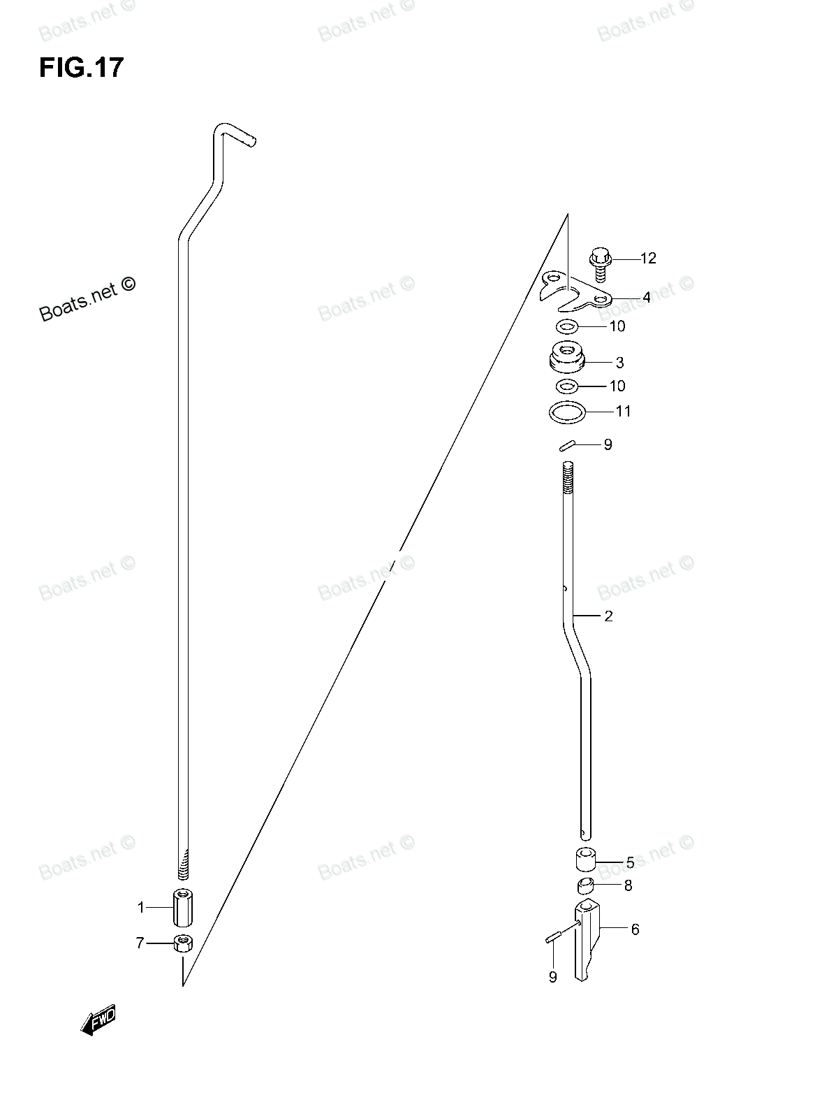
25111-95J20 ROD, SHIFT Suzuki
DF25(R)S, DF25R, DF25R
ROD

Price: query
Rating:
Number on catalog scheme: 2
Suzuki entire parts catalog list:
- CLUTCH ROD » 25111-95J20
- CLUTCH ROD » 25111-95J20
- CLUTCH ROD » 25111-95J20
Information:
Illustration 1 g03389877
Typical example
Use a suitable tool to remove temperature sensor (6) from the Clean Emissions Module (CEM).
Remove bolt (4) and the washer from the harness assembly clip (5).
Disconnect harness assembly (9) from harness assembly (10).
Cut cable straps (11) from harness assembly (10).Note: Ensure that all cable straps are removed for the harness assembly.
Remove bolts (1) and spacers (2) from bracket (3).
Remove bolts (8) and spacers (7) from bracket (3).
Remove bracket (3) from the CEM bracket.
Remove bolts (13) and spacers (14) (not shown) from bracket (12).
Illustration 2 g03389883
Use a suitable tool to remove temperature sensor (17) from the CEM.
Remove bolts (16) and spacers (15) from bracket (12).
Remove bracket (12) from bracket (18) for the CEM.
Illustration 3 g03389963
Make temporary marks on harness assembly (10) for installation purposes.
Make temporary mark on clip (5) for installation purposes. Remove clip (5) from harness assembly (10).
Cut cable straps (19) that secure harness assembly (10) to bracket (12).Note: Ensure that all cable straps are removed for the harness assembly.
Remove harness assembly (10) from bracket (12).Installation Procedure
Table 1
Required Tools
Tool Part Number Part Description Qty
A - Bostik Non Nickel
Anti-Seize Compound 1
Ensure that all components of the temperature sensor are clean and free from wear and damage. If any component of the temperature sensor is worn or damaged, the assembly of the temperature sensor must be replaced.
Illustration 4 g03389963
Position harness assembly (10) onto bracket (12). Ensure that harness assembly is correctly orientated onto the bracket.
Install new cable straps (19) that secure harness assembly (10) to bracket (12).Note: Ensure that the cable straps meet the Original Equipment Manufacturer (OEM) specification.
Install clip (5) from harness assembly (10). Ensure that the clip is correctly orientated.
Illustration 5 g03389883
Position bracket (12) onto bracket (18) for the CEM.
Install bolts (16) and spacers (15) from bracket (12) finger tight.
Apply Tooling (A) to the threads of temperature sensor (17).
Use a suitable tool to install temperature sensor (17) to the CEM. Tighten the temperature sensor to a torque of 45 N m (33 lb ft). Ensure that the temperature sensor does not come into contact with any part on the CEM.
Illustration 6 g03470560
Illustration 7 g03389877
Install bolts (13) and spacers (14) (not shown) to bracket (12) finger tight.
Tighten bolts (13) and bolts (16) to a torque of 12 N m (106 lb in).
Apply Tooling (A) to the threads of temperature sensor (6). Use a suitable tool to install temperature sensor (6) to the CEM.
Install bolt (4) and the washer to the harness assembly clip (5) hand tight. Ensure that the clip is correctly positioned.
Tighten the temperature sensor to a torque of 45 N m (33 lb ft). Ensure that the temperature sensor does not come into contact with any part on the CEM.
Tighten bolts (4) to a torque of 12 N m (106 lb in).
Position bracket (3) onto the CEM bracket.
Install bolts (1) and spacers (2) to bracket (3). Tighten the bolts to a torque of 12 N m (106 lb in).
Position harness assembly (10) onto bracket (3).
Install new cable straps (11) to harness assembly (10).Note: Ensure that cable straps meet the OEM specification.
Connect harness assembly (9) to harness assembly (10).
Turn the battery disconnect switch to the ON position.
Parts rod Suzuki:
15131-99E00
63220-96320
63220-96320 ROD, HANDLE
DF25, DF25(R)S, DF25Q, DF25Q(QR), DF25R, DF25R, DF25T, DF30, DF30Q, DF30Q(QR), DF30T
12894-95J00
23111-95J00
23111-95J10
57631-95J00