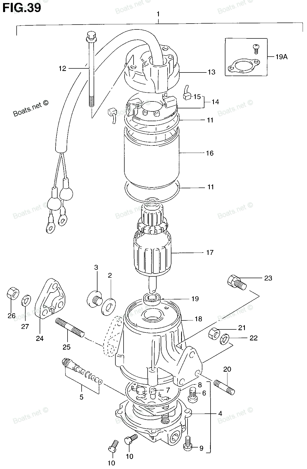
33899-94600 SEAL, PTT CABLE Suzuki
DT115, DT140, DT40C, DT75TCLJ, DT75TCLK, DT75TCLL, DT75TCLM, DT75TCLN, DT75TCLP, DT75TCLR, DT75TCLS, DT75TCLT, DT75TCLV, DT85TCLJ, DT85TCLK, DT85TCLL, DT85TCLM, DT85TCLN, DT85TCLP, DT85TCLR, DT85TCLS, DT85TCLT, DT85TCLV, DT85TCLW, DT85TCLX, DT85TCLY
SEAL

Price: query
Rating:
Number on catalog scheme: 19A
Compatible models:
Suzuki entire parts catalog list:
- POWER UNIT (MODEL:90~95) » 33899-94600
- POWER UNIT (MODEL:90~95) » 33899-94600
- POWER UNIT (MODEL:90~95) » 33899-94600
- POWER UNIT (MODEL:90~95) » 33899-94600
- POWER UNIT (DT40TC-MODEL:90~93) » 33899-94600
- POWER UNIT (DT40TC-MODEL:90~93) » 33899-94600
- POWER UNIT 90-94 » 33899-94600
- POWER UNIT 90-94 » 33899-94600
- POWER UNIT 90-94 » 33899-94600
- POWER UNIT 90-94 » 33899-94600
- POWER UNIT 90-94 » 33899-94600
- POWER UNIT 90-94 » 33899-94600
- POWER UNIT 90-94 » 33899-94600
- POWER UNIT 90-94 » 33899-94600
- POWER UNIT 90-94 » 33899-94600
- POWER UNIT 90-94 » 33899-94600
- POWER UNIT 90-94 » 33899-94600
- POWER UNIT 90-94 » 33899-94600
- POWER UNIT 90-94 » 33899-94600
- POWER UNIT 90-94 » 33899-94600
- POWER UNIT 90-94 » 33899-94600
- POWER UNIT 90-94 » 33899-94600
- POWER UNIT 90-94 » 33899-94600
- POWER UNIT 90-94 » 33899-94600
- POWER UNIT 90-94 » 33899-94600
- POWER UNIT 90-94 » 33899-94600
- POWER UNIT 90-94 » 33899-94600
- POWER UNIT 90-94 » 33899-94600
- POWER UNIT 90-94 » 33899-94600
Information:
start by:a) remove fuel injection pump housing and governorb) remove adapter housing and leversc) remove tachometer drive 1. Put the fuel injection pump and governor in position on tool (A).2. Remove cover (1) from over the torque spring.3. Remove bolts (2) that hold governor housing (3) to the fuel injection pump housing. Remove governor housing (3) from the fuel injection pump housing. 4. Remove spring (8), flat washer (7), wave washer (4), flat washer (5) and guide (6) from the governor housing. 5. If necessary remove lever (9) from the governor shaft. Put a mark on the shaft and the lever for correct installation.
Do not mix the sequence of insulators, shims, spacers, contact bar and spring when the torque stop is removed. For more information see REMOVE AND INSTALL TORQUE STOP.
6. Remove bolt (10) and nut (11) from torque spring (12). Remove torque spring (12). 7. Remove seat (13) and overfueling spring (14). 8. Push in on lever (16) and remove pin (15) from the fuel injection pump housing.9. Remove the ring that holds lever (16) to the dowel. Remove lever (16) from the dowel. 10. Remove riser (follower) (19) from the shaft. Shaft (17) has an O-ring seal on it which can make it difficult to remove the shaft from the fuel injection pump housing.11. Pull up on shaft (17) and remove the shaft and lever (18) from the fuel injection pump housing.
Tool (B) can cause damage to the cover. Always inspect the cover and install a new cover if needed.
12. Remove cover (20) for the flyweights with tool (B). 13. Install timing pin (21) or tool (C) so the camshaft will not turn.14. Remove the three bolts that hold the flyweight assembly to the camshaft. Remove flyweight assembly (22).15. Remove the timing pin or tool (C).Connection Of Fuel Injection Pump Housing And Governor
1. Put the fuel injection pump housing on tool (A).2. Install timing pin (1) or tool (C) to hold the camshaft so it will not turn.
Make sure the pin that holds the shaft in the flyweight assembly is in position before the flyweight assembly is installed.
3. Put flyweight assembly (2) in position on the camshaft. The bolts that hold the flyweight assembly to the camshaft have a locking material on the threads. The bolts must not be used more than one time.4. Install three new bolts that hold the flyweight assembly to the camshaft. Remove the timing pin or tool (C).
Never install a used flyweight cover that is bent.
5. Install cover (3) over the flyweight assembly with tool (B). 6. Grind a taper on the bottom edge of a 1/8" screwdriver (4). Install the screwdriver through the bolt hole in the fuel injection pump housing as shown. The screwdriver must fit evenly against the flyweight assembly cover. Make a mark (stake) in four places around the cover (3) in line with the groove in the camshaft. 7. Put lever (7) on the dowel. Install ring (6).8. Install pin (5) in the fuel injection pump housing with the round edge down. 9. Put riser (follower) (11) in position between the flyweights. Lift the flyweights up with a piece of wire and push the riser (follower) forward.
If lever (10) is not installed correctly, the governor can not operate and can cause the engine to overspeed.
10. Put lever (10) in position in the groove of riser (follower) (11) and the ball end engaged in the hole of sleeve shaft lever (8).11. Inspect the O-ring seal on shaft (9). Make a replacement if needed. Install shaft (9) to hold lever (10) in place. 12. Install overfueling spring (14) and seat (13) on the shaft.13. Install torque stop (12). 14. If lever (15) was removed, install lever (15) on the governor shaft. The lever must be 7° 5° to the left of the vertical centerline with the governor shaft at high idle. 15. Install guide (18), flat washer (17), wave washer (16), flat washer (19) and spring (20) in the governor housing. 16. Install cover (22) over the torque spring.17. Put a new gasket (21) on the governor housing and install governor housing (23) on the fuel injection pump housing. Install the bolts that hold it in place.end by:a) install tachometer driveb) install adapter housing and leversc) install fuel injection pump housing and governor
Parts seal Suzuki:
61622-94400
61622-94400 SEAL, RECOIL STARTER
DT25C, DT30C, DT30CRLJ, DT30CRSJ, DT30MCLJ, DT30MCSJ, DT35CRLH, DT35CRLJ, DT35CRLK, DT35CRSH, DT35CRSJ, DT35CRSK, DT35MCLH, DT35MCLJ, DT35MCLK, DT35MCSH, DT35MCSJ, DT35MCSK, DT35TCLH, DT35TCLJ, DT35TCLK, DT40C
61491-94400
61491-94400 SEAL, LID OIL FILLER
DT35CRLH, DT35CRLJ, DT35CRLK, DT35CRSH, DT35CRSJ, DT35CRSK, DT35MCLH, DT35MCLJ, DT35MCLK, DT35MCSH, DT35MCSJ, DT35MCSK, DT35TCLH, DT35TCLJ, DT35TCLK, DT40C
61622-95500
61410-94864-0ED
61113-94400
61113-94400 SEAL, ENGINE LOWER COVER
DT35CRLH, DT35CRLJ, DT35CRLK, DT35CRSH, DT35CRSJ, DT35CRSK, DT35MCLH, DT35MCLJ, DT35MCLK, DT35MCSH, DT35MCSJ, DT35MCSK, DT35TCLH, DT35TCLJ, DT35TCLK, DT40C
09284-08004
17500-94520
61112-94502