48500-94690-0ED SEAL SET, PTT CABLE Suzuki
DT115, DT140
SEAL

Price: query
Rating:
You can buy parts:
As an associate, we earn commssions on qualifying purchases through the links below

$249.00
12-07-2023
-: -
East Lake Marine Electric ELM Products Power Trim/Tilt 2-Wire Motor/Res/2,3 or 4-Hose Pump Compatible with Force and Suzuki O/B
East Lake Marine Electric is located in Oldsmar, FL. || 12V Power Trim/Tilt Motor/Reservoir/Pump Assembly for Mercury/Force || 2-wire motor and a 2-line hydraulic pump connection used on Force 85-150 HP 1986 – 1991. || This can also be used on Suzuki DT65, DT75, DT85, DT115 & DT140 1990-95 || Replaces Suzuki #’s 48500-94690-0ED, 48500-95290-0ED, 48500-95550-0ED, 485000-95680-0ED, 48500-94720-0ED & 48500-94790-0ED
East Lake Marine Electric is located in Oldsmar, FL. || 12V Power Trim/Tilt Motor/Reservoir/Pump Assembly for Mercury/Force || 2-wire motor and a 2-line hydraulic pump connection used on Force 85-150 HP 1986 – 1991. || This can also be used on Suzuki DT65, DT75, DT85, DT115 & DT140 1990-95 || Replaces Suzuki #’s 48500-94690-0ED, 48500-95290-0ED, 48500-95550-0ED, 485000-95680-0ED, 48500-94720-0ED & 48500-94790-0ED
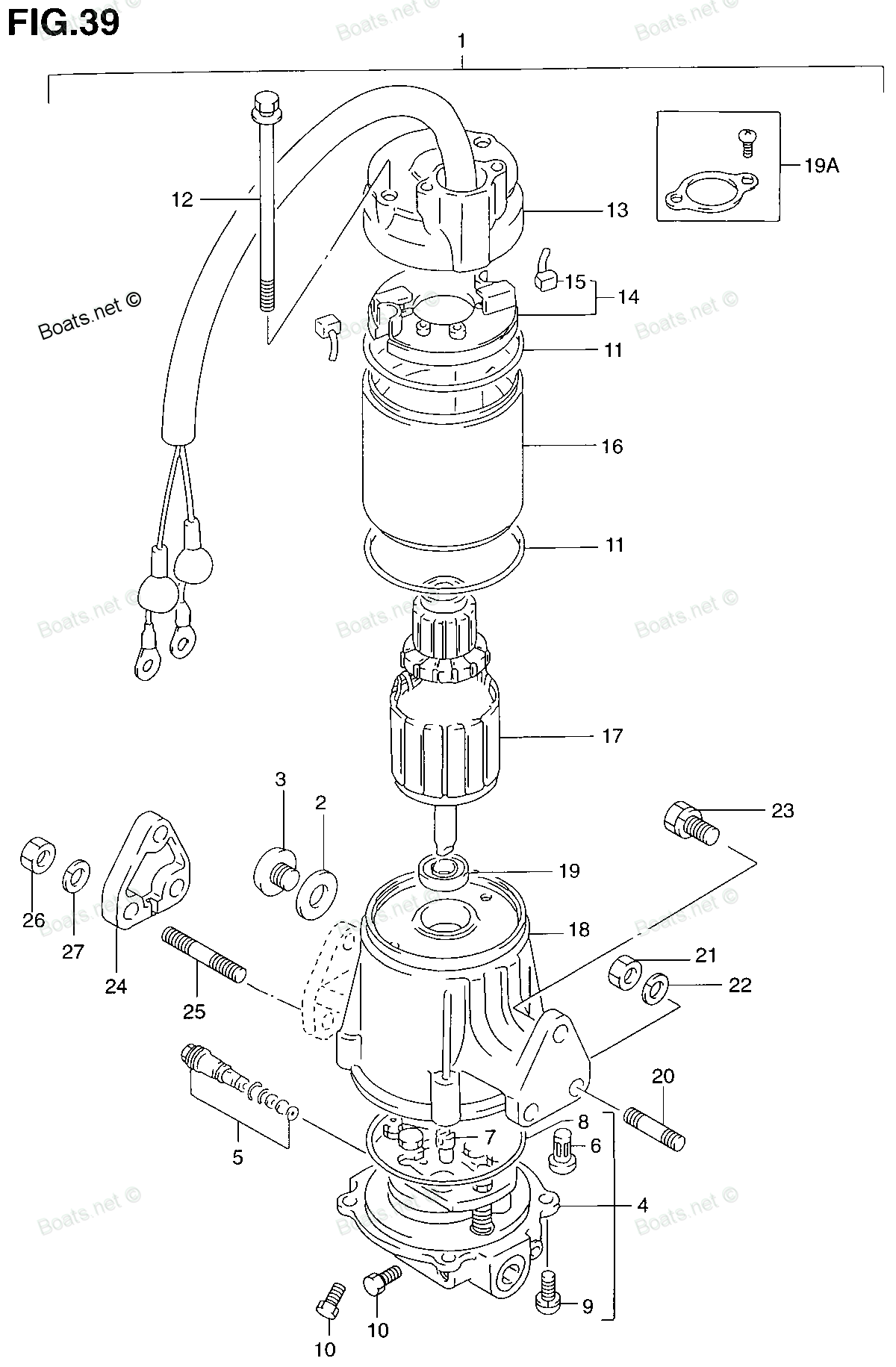
Number on catalog scheme: 1
Suzuki entire parts catalog list:
- POWER UNIT (MODEL:90~95) » 48500-94690-0ED
- POWER UNIT (MODEL:90~95) » 48500-94690-0ED
Information:
Start By:a. remove muffler1. Turn off the fuel supply at the fuel tank. Remove the fuel injection lines. 2. Disconnect fuel lines (1) and (2) at each end, and remove them from the fuel injection pump housing. Put plug and caps on all of the fuel line openings.3. Remove the cotter pin and pin (4), and disconnect rod end (3) from the governor. 4. Loosen bolt (5) and nut (6). Move the alternator toward the engine, and remove V-belt (7) from the alternator pulley.5. Remove the bolts that hold fan guard assembly (9) in position, and remove the fan guard assembly.6. Remove plug (8) from the timing gear cover.
Typical Example7. Loosen bolt (10) that holds the fuel pump drive gear to the fuel injection pump camshaft a maximum of one turn. Remove three bolts (11).8. Loosen three nuts (12) that hold the fuel injection pump to the timing gear plate. Loosen the nuts until they are even with the end of the studs.
Typical Example9. Install tool (A) in the timing gear cover. Tighten the forcing screw in tool (A), and loosen the drive gear from the fuel injection pump camshaft, them remove tool (A) from the timing gear cover.10. Remove the bolt and washer from the fuel injection pump camshaft.11. Remove three nuts (12), and remove the fuel injection pump housing and governor from the engine. The weight of the fuel injection pump housing and governor is 22 kg (49 lb.).12. Remove the O-ring seals from the fuel injection pump housing.Install Fuel Injection Pump Housing And Governor
1. Install the fuel injection pump housing and governor on tooling (A), or use a suitable vise to hold it.2. Remove the bolts and cover over the timing pin hole in the pump housing.3. Install the washer and bolt (1) that is used to hold the drive gear to the fuel injection pump camshaft.4. Install tool (B) in the hole of the fuel injection pump housing. Use bolt (1), and turn the fuel injection pump camshaft until tool (B) engages in the notch in the camshaft.5. Remove the bolt and washer from the camshaft.6. Remove the fuel injection pump housing and governor from tooling (A). 7. Install O-ring seals (2) and (3) in the fuel injection pump housing. Put clean engine oil on the O-ring seals. 8. Put the fuel injection pump housing and governor in position on the engine, and install three nuts (4).9. Put clean oil on the threads of bolt (1). Install the bolt and washer to hold the drive gear to the fuel injection pump camshaft. Tighten the bolt finger tight only. Bolt (1) must be tight enough to hold the gear clearance (backlash) out of the timing gears when the engine is turned. However, the timing gear must be able to turn on the shaft when the engine is turned to put the No. 1 piston on the top center compression position (TDC). 10. Put No. 1 piston at the top center compression position (TDC) with the following procedure:a. Remove plug (5) from the flywheel housing.b. Turn the crankshaft clockwise (as seen from the front of the engine) until a 3/8"-16 × 2 in. (50.8 mm) bolt can be installed through the timing hole in the flywheel housing and into the hole in the flywheel. c. Remove the valve cover from the valve cover base. Check to see if both rocker arms (6) for the No. 1 piston can be moved backward and forward by hand. The No. 1 piston is at the top center compression position when the bolt is installed in the flywheel, and both rocker arms for No. 1 piston can be moved backward and forward. If both rocker arms cannot be moved, the No. 1 piston is not at the top center compression position. Remove the bolt from the flywheel. Turn the crankshaft clockwise (as seen from the front of the engine) one full turn (360°), and install the bolt again.11. With the timing pin in the notch of the fuel injection pump camshaft and the timing bolt in the flywheel, tighten the bolt which holds the drive gear to the fuel injection pump camshaft to a torque of 175 7 N m (129 5 lb.ft.).12. Check the timing as follows:a. Remove both the timing pin and timing bolt.b. Turn the crankshaft clockwise (as seen from the front of the engine) two full turns, and install the timing pin and bolt again.c. The timing is correct if both the timing pin and timing bolt can be installed at the same time. The timing procedure must be done again if the timing pin and timing bolt cannot be installed at the same time.d. Remove the timing pin and timing bolt when the timing is correct.13. Install the plug in the flywheel housing. 14. Install three bolts (7).15. Put the gasket and cover (8) in position on the fuel injection pump housing, and install the bolts that hold them in place. 16. Install plug (12) in the timing gear cover.17. Put V-belt (11) in position on the alternator pulley. Adjust the belt tension, and tighten bolts (9) and (10).18. Use a belt tension gauge, such as a Borroughs Tool Company part No. BT-33-95, to check the belt tension. The gauge reading should be 534 22 N (120 5 lb.) for a new belt and 400 44 N (90 10 lb.) for a used belt.19. Install guard assembly (13) on the radiator. 20. Put rod end (15) in position, and install the pin (16) and the cotter pin to hold it in place.21. Connect fuel line (17).22. Install fuel lines (14). Install the clips and bolt to hold fuel lines (14) and (17) in position.23. Turn on the fuel supply at the fuel tank. Remove the air from the fuel system.End By:a. install fuel linesb. install muffler
Parts seal Suzuki:
13851-95210
12322-94600
12323-94600
09283-40024
52173-94502
09284-08004
17500-94520
61112-94502