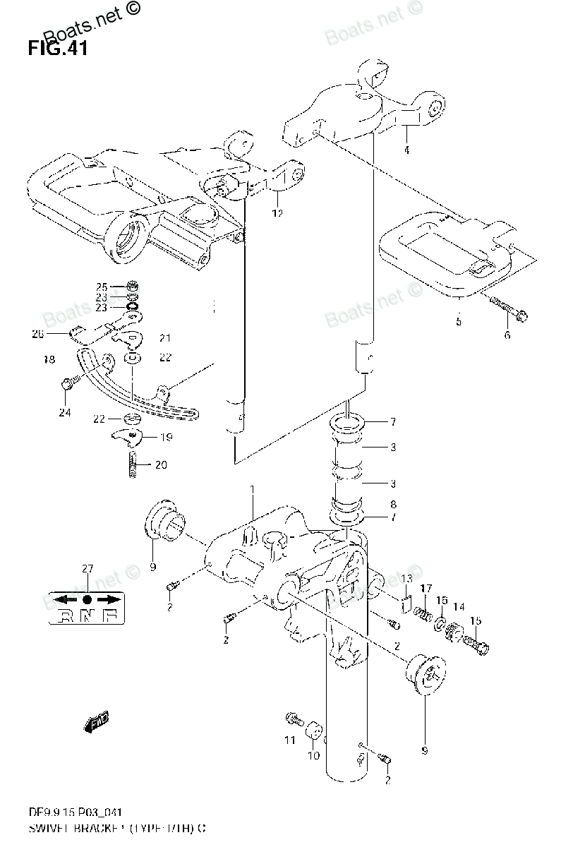
43512-94J00 SHAFT, STEERING ADJUSTER Suzuki
DF15, DF15, DF15S, DF9.9R, DF9.9RL, DF9.9S, DF9.9TH, DF9.9TH, DF99R, DF99TH
SHAFT

Price: query
Rating:
Number on catalog scheme: 20
Suzuki entire parts catalog list:
- SWIVEL BRACKET (TYPE:T-TH) » 43512-94J00
- SWIVEL BRACKET (MODEL:05-) » 43512-94J00
- SWIVEL BRACKET (MODEL:05-09) » 43512-94J00
- SWIVEL BRACKET (MODEL:05-) » 43512-94J00
- SWIVEL BRACKET (TYPE:T-TH) » 43512-94J00
- SWIVEL BRACKET (MODEL:05-07) » 43512-94J00
- SWIVEL BRACKET (MODEL:05-09) » 43512-94J00
- SWIVEL BRACKET (TYPE:T-TH) » 43512-94J00
- SWIVEL BRACKET (MODEL:05-) » 43512-94J00
- SWIVEL BRACKET (MODEL:05-07) » 43512-94J00
- SWIVEL BRACKET (MODEL:05-07) » 43512-94J00
- SWIVEL BRACKET (MODEL:05-) » 43512-94J00
- SWIVEL BRACKET (MODEL:05-09) » 43512-94J00
- SWIVEL BRACKET (TYPE:T-TH) » 43512-94J00
- SWIVEL BRACKET (TYPE:T-TH) » 43512-94J00
- SWIVEL BRACKET (MODEL:05-) » 43512-94J00
- SWIVEL BRACKET (MODEL:05-10) » 43512-94J00
- SWIVEL BRACKET (TYPE:T-TH) » 43512-94J00
- SWIVEL BRACKET (MODEL:05-10) » 43512-94J00
- SWIVEL BRACKET (TYPE:T-TH) » 43512-94J00
Information:
Illustration 1 g01240739
Schematic for the pressure sensor supply
Test Step 1. Inspect the Electrical Connectors and the Wiring
Remove electrical power from the ECM.
Illustration 2 g01240816
Sensor locations for the pressure sensor supply
(1) Intake manifold pressure sensor
(2) Fuel pressure sensor
(3) Atmospheric pressure sensor
(4) Engine oil pressure sensor
(5) J2/P2 ECM connectors
Thoroughly inspect connectors (5). Also, thoroughly inspect the connectors for sensors (1), (2), (3), and (4). Refer to Troubleshooting, "Electrical Connectors - Inspect" for details.
Illustration 3 g01204484
P2 ECM connector
(P2-15) Intake manifold pressure sensor
(P2-17) Sensor return
(P2-28) Engine oil pressure sensor
(P2-40) Fuel pressure sensor
(P2-57) Atmospheric pressure sensor
(P2-72) Pressure sensor supply
Illustration 4 g01240891
Sensor connector
(1) Pressure sensor supply
(2) Sensor return
(3) Sensor signal
Perform a 45 N (10 lb) pull test on each of the wires in the ECM connector and on each of the wires in the pressure sensor connectors.
Check the allen head screw for each of the ECM connectors and the machine connectors for the proper torque. Refer to Troubleshooting, "Electrical Connectors - Inspect" for the correct torque values.
Check the harness and wiring for abrasions and for pinch points from each of the pressure sensors back to the ECM. Expected Result:All connectors, pins and sockets are completely coupled and/or inserted and the harness and wiring are free of corrosion, of abrasion or of pinch points.Results:
OK - The harness and connectors appear to be OK. Proceed to Test Step 2.
Not OK - There is a problem with the connectors and/or wiring.Repair: Repair the connectors or wiring and/or replace the connectors or wiring. Ensure that all of the seals for each of the connectors are properly in place and ensure that the connectors are completely coupled. Verify that the repair eliminates the problem.STOPTest Step 2. Check for Active Diagnostic Codes
Connect Caterpillar Electronic Technician (ET) to the service tool connector.
Restore electrical power to the ECM.
Monitor the active diagnostic code screen on Cat ET. Check for an active 262-03 code or an active 262-04 code. Note: Wait at least 30 seconds in order for the diagnostic codes to become active.
Remove electrical power from the ECM. Expected Result:No diagnostic codes are active.Results:
OK - No diagnostic codes are active.Repair: If any of the above codes are logged and the engine is not running properly, refer to Troubleshooting, "Troubleshooting Without a Diagnostic Code".If the engine is running properly at this time, there may be an intermittent problem in a harness that is causing the codes to be logged. Refer to Troubleshooting, "Electrical Connectors - Inspect".STOP
Not OK - Either the 262-03 or 262-04 diagnostic code is active at this time. Proceed to Test Step 3.Test Step 3. Disconnect the Pressure Sensors and Check for Active Diagnostic Codes
Restore electrical power to the ECM.
Monitor the active diagnostic code screen on Cat ET while you disconnect each pressure sensor connector. Check for an active 262-03 code or an active 262-04 code. Note: Wait at least 30 seconds in order for the diagnostic codes to become active.
Disconnect the following sensors one at a time:
Engine oil pressure sensor
Intake manifold pressure sensor
Fuel pressure sensor
Atmospheric pressure sensorExpected Result:The diagnostic code deactivates when a particular sensor is disconnected.Results:
OK - The 262-03 or 262-04 diagnostic code deactivates when a particular sensor is disconnected.Repair: Connect the suspect sensor. If the code returns, replace the sensor. Connect all of the connectors. Verify that the problem is resolved.STOP
Not OK - The 262-03 or 262-04 diagnostic code remains active after all of the sensors are disconnected. Leave the sensors disconnected. The sensors are not the cause of the diagnostic code. Remove electrical power from the ECM. Proceed to Test Step 4.Test Step 4. Check the Supply Voltages at the ECM
Disconnect the J2/P2 ECM connectors.
Fabricate two jumper wires that are long enough to be used to measure the supply voltage at the ECM connectors. Crimp connector sockets to one end of each jumper wire.
Remove the wires from terminal locations P2-72 (pressure sensor supply) and P2-17 (sensor return). Install a jumper wire into each of these terminal locations.
Connect the J2/P2 ECM connectors.
Restore electrical power to the ECM.
Measure the voltage between the jumper wire in P2-72 (pressure sensor supply) and the jumper wire in P2-17 (sensor return).
Remove electrical power from the ECM. Expected Result:Each voltage measurement is 5.0 0.2 VDC.Results:
OK - The voltage measurement is 5.0 0.2 VDC. The ECM is operating correctly.Repair: The supply wires are shorted to another wire in the harness or the supply wires are shorted to engine ground. Repair the wiring and/or the connector. Replace parts, if necessary. Verify that the problem is resolved.STOP
Not OK - The voltage measurement is not 5.0 0.2 VDC.Repair: There is a problem with the ECM. Replace the ECM. Refer to Troubleshooting, "Replacing the ECM".STOP
Parts shaft Suzuki:
57610-93901

57610-93901 Shaft, Propeller
DF15, DF15, DF15, DF15S, DF9.9, DF9.9R, DF9.9RL, DF9.9S, DF9.9TH, DF9.9TH, DF99R, DF99TH, DT15C, DT15ELG, DT15ELH, DT15ELJ, DT15ESG, DT15ESH, DT15ESJ, DT15MLG, DT15MLH, DT15MLJ, DT15MSG, DT15MSH, DT15MSJ, DT9.9ELG, DT9.9ELH, DT9.9ESG, DT9.9ESH, DT9.9
48321-97E01
48321-97E01 SHAFT, TILT CYLINDER UPPER
DF15, DF15, DF15, DF40, DF40, DF40QH, DF40TL, DF50, DF50, DF50QH, DF50TL, DF9.9, DF9.9R, DF9.9TH, DF9.9TH, DF99R, DF99TH
31341-94J00
31341-94J00 SHAFT, PINION
DF15, DF15, DF15, DF15A, DF15S, DF20A, DF25(R)S, DF25R, DF25R, DF40, DF40, DF40A, DF40A, DF40QH, DF40TL, DF50, DF50, DF50A, DF50A, DF50QH, DF50TL, DF60A, DF60A, DF8A, DF8AR, DF9.9, DF9.9A, DF9.9AR, DF9.9R, DF9.9RL, DF9.9S, DF9.9TH, DF9.9TH, DF99AR, D
12861-93E00
12861-93E00 SHAFT, ROCKER ARM
DF15, DF15, DF15, DF15S, DF9.9, DF9.9R, DF9.9RL, DF9.9S, DF9.9TH, DF9.9TH, DF99R, DF99TH
41130-94J00
41130-94J00 SHAFT, CLAMP BRKT
DF15, DF15, DF15S, DF9.9R, DF9.9RL, DF9.9S, DF9.9TH, DF9.9TH, DF99R, DF99TH
41130-93E00
41130-93E00 SHAFT, CLAMP BRKT
DF15, DF15, DF15S, DF9.9R, DF9.9RL, DF9.9S, DF9.9TH, DF9.9TH, DF99R, DF99TH
57100-93912

57100-93912 SHAFT ASSY, DRIVE (S)
DF15, DF15, DF15, DF15S, DF9.9, DF9.9R, DF9.9RL, DF9.9S, DF9.9TH, DF9.9TH, DF99R, DF99TH
57100-93902

57100-93902 SHAFT ASSY, DRIVE (L)
DF15, DF15, DF15, DF15S, DF9.9, DF9.9R, DF9.9RL, DF9.9S, DF9.9TH, DF9.9TH, DF99R, DF99TH