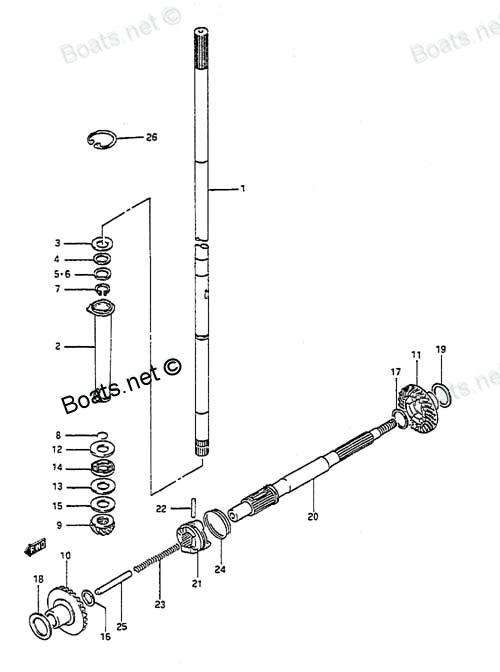
09202-04018 SHIFTER PIN Suzuki
DT8CENK, DT8CENL, DT8CLJ, DT8CLK, DT8CLL, DT8CLM, DT8CNK, DT8CNL, DT8CSJ, DT8CSL, DT8CSM, DT8MCLN, DT8MCLP, DT8MCLS, DT8MCLT, DT8MCLV, DT8MCSN, DT8MCSP, DT8MCSR, DT8MCSS, DT8MCST, DT8MCSV, DT8MSLR, DT8SCK, DT9.9 CELK, DT9.9CELJ, DT9.9CELL, DT9.9CELM,
SHIFTER

Price: query
Rating:
Number on catalog scheme: 22
Compatible models:
DT8CENK
DT8CENL
DT8CLJ
DT8CLK
DT8CLL
DT8CLM
DT8CNK
DT8CNL
DT8CSJ
DT8CSL
DT8CSM
DT8MCLN
DT8MCLP
DT8MCLS
DT8MCLT
DT8MCLV
DT8MCSN
DT8MCSP
DT8MCSR
DT8MCSS
DT8MCST
DT8MCSV
DT8MSLR
DT8SCK
DT9.9 CELK
DT9.9CELJ
DT9.9CELL
DT9.9CELM
DT9.9CELN
DT9.9CELP
DT9.9CELR
DT9.9CELS
DT9.9CELT
DT9.9CENK
DT9.9CESJ
DT9.9CESK
DT9.9CESL
DT9.9CESM
DT9.9CESN
DT9.9CESP
DT9.9CESR
DT9.9CESS
DT9.9CEST
DT9.9CNELP
DT9.9CNELR
DT9.9CNELS
DT9.9CNELT
DT9.9CNEXP
DT9.9CNEXR
DT9.9CNEXS
DT9.9CNEXT
DT9.9CNEXV
DT9.9CNJ
DT9.9CNK
DT9.9CNL
DT9.9CNLN
DT9.9MCLJ
DT9.9MCLK
DT9.9MCLL
DT9.9MCLM
DT9.9MCLN
DT9.9MCLP
DT9.9MCLR
DT9.9MCLS
DT9.9MCLT
DT9.9MCLV
DT9.9MCNLR
DT9.9MCNLT
DT9.9MCNLV
DT9.9MCSJ
DT9.9MCSK
DT9.9MCSL
DT9.9MCSM
DT9.9MCSN
DT9.9MCSP
DT9.9MCSR
DT9.9MCSS
DT9.9MCST
DT9.9MCSV
Suzuki
Suzuki entire parts catalog list:
- TRANSMISSION » 09202-04018
- TRANSMISSION » 09202-04018
- TRANSMISSION » 09202-04018
- TRANSMISSION » 09202-04018
- TRANSMISSION » 09202-04018
- TRANSMISSION » 09202-04018
- TRANSMISSION » 09202-04018
- TRANSMISSION » 09202-04018
- TRANSMISSION » 09202-04018
- TRANSMISSION » 09202-04018
- TRANSMISSION » 09202-04018
- TRANSMISSION » 09202-04018
- TRANSMISSION » 09202-04018
- TRANSMISSION » 09202-04018
- TRANSMISSION » 09202-04018
- TRANSMISSION » 09202-04018
- TRANSMISSION » 09202-04018
- TRANSMISSION » 09202-04018
- TRANSMISSION » 09202-04018
- TRANSMISSION » 09202-04018
- TRANSMISSION » 09202-04018
- TRANSMISSION » 09202-04018
- TRANSMISSION » 09202-04018
- TRANSMISSION » 09202-04018
- TRANSMISSION » 09202-04018
- TRANSMISSION » 09202-04018
- TRANSMISSION » 09202-04018
- TRANSMISSION » 09202-04018
- TRANSMISSION » 09202-04018
- TRANSMISSION » 09202-04018
- TRANSMISSION » 09202-04018
- TRANSMISSION » 09202-04018
- TRANSMISSION » 09202-04018
- TRANSMISSION » 09202-04018
- TRANSMISSION » 09202-04018
- TRANSMISSION » 09202-04018
- TRANSMISSION » 09202-04018
- TRANSMISSION » 09202-04018
- TRANSMISSION » 09202-04018
- TRANSMISSION » 09202-04018
- TRANSMISSION » 09202-04018
- TRANSMISSION » 09202-04018
- TRANSMISSION » 09202-04018
- TRANSMISSION » 09202-04018
- TRANSMISSION » 09202-04018
- TRANSMISSION » 09202-04018
- TRANSMISSION » 09202-04018
- TRANSMISSION » 09202-04018
- TRANSMISSION » 09202-04018
- TRANSMISSION » 09202-04018
- TRANSMISSION » 09202-04018
- TRANSMISSION » 09202-04018
- TRANSMISSION » 09202-04018
- TRANSMISSION » 09202-04018
- TRANSMISSION » 09202-04018
- TRANSMISSION » 09202-04018
- TRANSMISSION » 09202-04018
- TRANSMISSION » 09202-04018
- TRANSMISSION » 09202-04018
- TRANSMISSION » 09202-04018
- TRANSMISSION » 09202-04018
- TRANSMISSION » 09202-04018
- TRANSMISSION » 09202-04018
- TRANSMISSION » 09202-04018
- TRANSMISSION » 09202-04018
- TRANSMISSION » 09202-04018
- TRANSMISSION » 09202-04018
- TRANSMISSION » 09202-04018
- TRANSMISSION » 09202-04018
- TRANSMISSION » 09202-04018
- TRANSMISSION » 09202-04018
- TRANSMISSION » 09202-04018
- TRANSMISSION » 09202-04018
- TRANSMISSION » 09202-04018
- TRANSMISSION » 09202-04018
- TRANSMISSION » 09202-04018
- TRANSMISSION » 09202-04018
- TRANSMISSION » 09202-04018
- TRANSMISSION » 09202-04018
Information:
Illustration 1 g01021887
Typical example
(1) Brake housing assembly
(2) Bolts
(3) Slave piston
(4) Solenoid valve
(5) Exhaust valve bridges
(6) Stud, spacer and nut The compression brake consists of three identical housing assemblies (1). A brake housing is installed in each of the valve mechanism compartments. The brake is located above the rocker arms and the rocker arm shaft. Each housing assembly is positioned over two cylinders. The housing is mounted to the support for the rocker arm shaft with bolts (2). The housing is supported on the cylinder head with one stud, one spacer, and one nut (6). The exhaust rocker arm is used to transmit force from slave piston (3) to the exhaust valve. A lead wire carries the signal of the compression brake to solenoid valve (4). Each lead wire activates the compression brake on two cylinders of the engine.Note: Only the valve mechanism that is for the exhaust is used in the operation of the compression brake.Note: The slave piston pushes on the rocker arm for the exhaust valves. The rocker arm depresses BOTH exhaust valves of each cylinder during the operation of the compression brake.The control circuit for the compression brake provides progressive braking capability. The control circuit for the compression brake permits the operation of one, two, or all three of the compression brakes. Therefore, the compression brake can be activated on two cylinders, four cylinders, or six cylinders of the engine.Compression Brake Operation
Illustration 2 g01023115
Master-slave circuit schematic
(1) Ground wire
(2) Solenoid valve
(3) Lead wire from the ECM
(4) Lead wire to the sensor for the ECM
(5) Spring
(6) Control valve
(7) High pressure oil passage
(8) Slave piston adjustment screw
(9) Slave piston
(10) Master piston
(11) Oil passage in the rocker arm shaft
(12) Engine oil pump
(13) Spring
(14) Rocker arm for the electronic unit injector
(15) Engine oil pan
(16) Oil drain passage
(17) Low pressure oil passage
(18) Ball check valve
(19) Exhaust valve bridge
(20) Exhaust valves
(21) Rocker arm for the exhaust valve
(22) Camshaft The compression brake operates on engine oil. The engine oil is supplied around the bolts through the rocker arm shafts. Solenoid valve (2) controls the oil flow in the compression brake housing assembly.The solenoid is activated by a signal from the ECM. Solenoid valve (2) moves down when the compression brake is activated. Solenoid valve (2) closes oil drain passage (16) to engine oil pan (15). Solenoid valve (2) also opens low pressure oil passage (17) to control valve (6). As low pressure oil passage (17) is filled with engine oil, the control valve is pushed up in the chamber against the force of spring (5). In the up position, a groove in control valve (6) is in alignment with high pressure oil passage (7) that supplies slave piston (9) and master piston (10). The engine oil pressure will now lift ball check valve (18). High pressure oil passage (7) is filled with the engine oil from passage (17). The chambers behind the slave piston and the master piston are also filled. This pressure moves the master piston downward until contact is made with electronic unit injector rocker arm (14). Ball check valve (18) is seated as the upward motion is initiated on the master piston. Ball check valve (18) is closed by an increase in pressure from the movement of the master cylinder. The system is now in operation. When the solenoid is activated, the compression brake is ready to operate in approximately 1/5 of a second.When camshaft (22) begins to move up on pumping stroke of the electronically controlled unit injector, electronic unit injector rocker arm (14) makes contact with extending master piston (10). As the master piston begins to move up, the oil pressure increases in high pressure oil passage (7). The pressure increases because ball check valve (18) will not allow the oil to escape. The slave piston is forced down against the exhaust rocker arm because of a constant increase in pressure on the upward movement of the electronic unit injector rocker arm. The force is great enough to open exhaust valves (20).Master piston (10) is moved only when the engine cylinder is on the compression stroke. Slave piston (9) opens the two exhaust valves of the same cylinder only on the compression stroke. The exhaust valves are opened immediately before the top center of the compression stroke. The braking force is constant. The operation of the compression brake is caused by the motion of the valve mechanism for the same cylinder. The sequence for the operation of the compression brake is the same sequence as the firing order of the engine.When solenoid valve (2) is in the off position, the engine oil supply passage is closed, and the oil drain passage (16) is opened. The oil will drain from control valve (6). Spring (5) will then push the control valve to the bottom of the chamber. The oil from high pressure oil passage (7) will now drain into the chamber that is above the piston for the control valve. Spring (13) now moves master piston (10) up to the retracted position. The master piston will no longer be in contact with electronic unit injector rocker arm (14). The time that is necessary for the system to stop the operation is approximately 1/10 of a second. The compression brake will not be able to operate now until solenoid valve (2) is activated again by the ECM.Slave piston adjustment screw (8) is used to set the clearance (lash) between the compression brake and the rocker arm assemblies. Refer to Testing and Adjusting, "Compression Brake" for information on the adjustment of the compression brake. The correct adjustment will optimize the brake performance without overstressing the engine components.
Parts shifter Suzuki:
09440-27011
09440-27011 SHIFTER SPRING
DT8CENK, DT8CENL, DT8CLJ, DT8CLK, DT8CLL, DT8CLM, DT8CNK, DT8CNL, DT8CSJ, DT8CSL, DT8CSM, DT8MCLN, DT8MCLP, DT8MCLS, DT8MCLT, DT8MCLV, DT8MCSN, DT8MCSP, DT8MCSR, DT8MCSS, DT8MCST, DT8MCSV, DT8MSLR, DT8SCK, DT9.9 CELK, DT9.9CELJ, DT9.9CELL, DT9.9CELM,