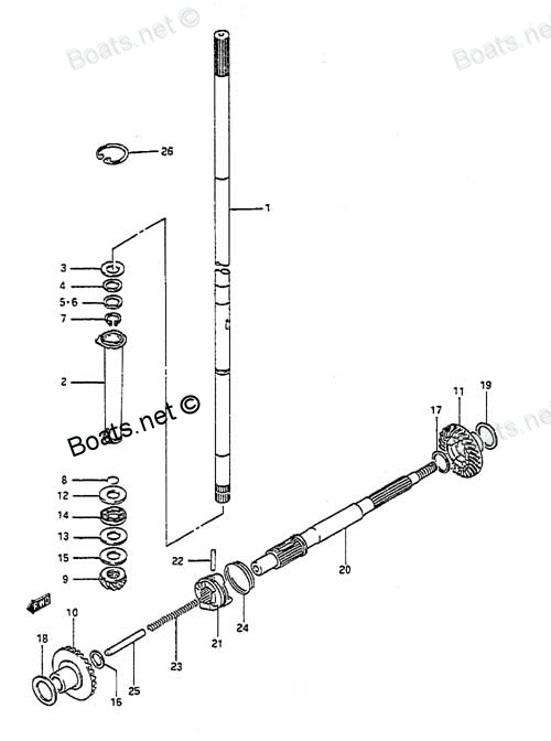
09440-27011 SHIFTER SPRING Suzuki
DT8CENK, DT8CENL, DT8CLJ, DT8CLK, DT8CLL, DT8CLM, DT8CNK, DT8CNL, DT8CSJ, DT8CSL, DT8CSM, DT8MCLN, DT8MCLP, DT8MCLS, DT8MCLT, DT8MCLV, DT8MCSN, DT8MCSP, DT8MCSR, DT8MCSS, DT8MCST, DT8MCSV, DT8MSLR, DT8SCK, DT9.9 CELK, DT9.9CELJ, DT9.9CELL, DT9.9CELM,
SHIFTER

Price: query
Rating:
Number on catalog scheme: 24
Compatible models:
DT8CENK
DT8CENL
DT8CLJ
DT8CLK
DT8CLL
DT8CLM
DT8CNK
DT8CNL
DT8CSJ
DT8CSL
DT8CSM
DT8MCLN
DT8MCLP
DT8MCLS
DT8MCLT
DT8MCLV
DT8MCSN
DT8MCSP
DT8MCSR
DT8MCSS
DT8MCST
DT8MCSV
DT8MSLR
DT8SCK
DT9.9 CELK
DT9.9CELJ
DT9.9CELL
DT9.9CELM
DT9.9CELN
DT9.9CELP
DT9.9CELR
DT9.9CELS
DT9.9CELT
DT9.9CENK
DT9.9CESJ
DT9.9CESK
DT9.9CESL
DT9.9CESM
DT9.9CESN
DT9.9CESP
DT9.9CESR
DT9.9CESS
DT9.9CEST
DT9.9CNELP
DT9.9CNELR
DT9.9CNELS
DT9.9CNELT
DT9.9CNEXP
DT9.9CNEXR
DT9.9CNEXS
DT9.9CNEXT
DT9.9CNEXV
DT9.9CNJ
DT9.9CNK
DT9.9CNL
DT9.9CNLN
DT9.9MCLJ
DT9.9MCLK
DT9.9MCLL
DT9.9MCLM
DT9.9MCLN
DT9.9MCLP
DT9.9MCLR
DT9.9MCLS
DT9.9MCLT
DT9.9MCLV
DT9.9MCNLR
DT9.9MCNLT
DT9.9MCNLV
DT9.9MCSJ
DT9.9MCSK
DT9.9MCSL
DT9.9MCSM
DT9.9MCSN
DT9.9MCSP
DT9.9MCSR
DT9.9MCSS
DT9.9MCST
DT9.9MCSV
Suzuki
Suzuki entire parts catalog list:
- TRANSMISSION » 09440-27011
- TRANSMISSION » 09440-27011
- TRANSMISSION » 09440-27011
- TRANSMISSION » 09440-27011
- TRANSMISSION » 09440-27011
- TRANSMISSION » 09440-27011
- TRANSMISSION » 09440-27011
- TRANSMISSION » 09440-27011
- TRANSMISSION » 09440-27011
- TRANSMISSION » 09440-27011
- TRANSMISSION » 09440-27011
- TRANSMISSION » 09440-27011
- TRANSMISSION » 09440-27011
- TRANSMISSION » 09440-27011
- TRANSMISSION » 09440-27011
- TRANSMISSION » 09440-27011
- TRANSMISSION » 09440-27011
- TRANSMISSION » 09440-27011
- TRANSMISSION » 09440-27011
- TRANSMISSION » 09440-27011
- TRANSMISSION » 09440-27011
- TRANSMISSION » 09440-27011
- TRANSMISSION » 09440-27011
- TRANSMISSION » 09440-27011
- TRANSMISSION » 09440-27011
- TRANSMISSION » 09440-27011
- TRANSMISSION » 09440-27011
- TRANSMISSION » 09440-27011
- TRANSMISSION » 09440-27011
- TRANSMISSION » 09440-27011
- TRANSMISSION » 09440-27011
- TRANSMISSION » 09440-27011
- TRANSMISSION » 09440-27011
- TRANSMISSION » 09440-27011
- TRANSMISSION » 09440-27011
- TRANSMISSION » 09440-27011
- TRANSMISSION » 09440-27011
- TRANSMISSION » 09440-27011
- TRANSMISSION » 09440-27011
- TRANSMISSION » 09440-27011
- TRANSMISSION » 09440-27011
- TRANSMISSION » 09440-27011
- TRANSMISSION » 09440-27011
- TRANSMISSION » 09440-27011
- TRANSMISSION » 09440-27011
- TRANSMISSION » 09440-27011
- TRANSMISSION » 09440-27011
- TRANSMISSION » 09440-27011
- TRANSMISSION » 09440-27011
- TRANSMISSION » 09440-27011
- TRANSMISSION » 09440-27011
- TRANSMISSION » 09440-27011
- TRANSMISSION » 09440-27011
- TRANSMISSION » 09440-27011
- TRANSMISSION » 09440-27011
- TRANSMISSION » 09440-27011
- TRANSMISSION » 09440-27011
- TRANSMISSION » 09440-27011
- TRANSMISSION » 09440-27011
- TRANSMISSION » 09440-27011
- TRANSMISSION » 09440-27011
- TRANSMISSION » 09440-27011
- TRANSMISSION » 09440-27011
- TRANSMISSION » 09440-27011
- TRANSMISSION » 09440-27011
- TRANSMISSION » 09440-27011
- TRANSMISSION » 09440-27011
- TRANSMISSION » 09440-27011
- TRANSMISSION » 09440-27011
- TRANSMISSION » 09440-27011
- TRANSMISSION » 09440-27011
- TRANSMISSION » 09440-27011
- TRANSMISSION » 09440-27011
- TRANSMISSION » 09440-27011
- TRANSMISSION » 09440-27011
- TRANSMISSION » 09440-27011
- TRANSMISSION » 09440-27011
- TRANSMISSION » 09440-27011
- TRANSMISSION » 09440-27011
Information:
Table 1
Required Tools
Part Number Part Name Quantity
1U-5470
or
198-4240 Engine Pressure Group
or
Digital Pressure Indicator 1
Illustration 1 g00293196
1U-5470 Engine Pressure Group
Refer to Special Instruction, SEHS8907, "Using the 1U-5470 Engine Pressure Group" for the instructions that are needed to use the 1U-5470 Engine Pressure Group. Refer to Operation Manual, NEHS0818, "Using the 198-4240 Pressure Indicator Tool Gp" for the instructions that are needed to use the 198-4240 Pressure Indicator Tool Gp.
Inspect the engine air cleaner inlet and ducting in order to ensure that the passageway is not blocked or collapsed.
Inspect the engine air cleaner element. Replace a dirty engine air cleaner element with a clean engine air cleaner element.
Check for dirt tracks on the clean side of the engine air cleaner element. If dirt tracks are observed, contaminants are flowing past the engine air cleaner element and/or the seal for the engine air cleaner element.
Hot engine components can cause injury from burns. Before performing maintenance on the engine, allow the engine and the components to cool.
Making contact with a running engine can cause burns from hot parts and can cause injury from rotating parts.When working on an engine that is running, avoid contact with hot parts and rotating parts.
Use the differential pressure gauge of the 1U-5470 Engine Pressure Group.
Illustration 2 g01099496
Right side view of engine
(1) Air cleaner
(2) Test location
Connect the vacuum port of the differential pressure gauge to test location (2). Test location (2) can be located anywhere along the air inlet piping after the engine air cleaner but before the turbocharger.
Leave the pressure port of the differential pressure gauge open to the atmosphere.
Start the engine. Run the engine in the no-load condition at high idle.
Record the value.
Multiply the value from Step 4.d by 1.8.
Compare the result from Step 4.e to the appropriate values that follow. The air flow through a used engine air cleaner may have a restriction. The air flow through a plugged engine air cleaner will be restricted to some magnitude. In either case, the restriction must not be more than the following amount: Maximum restriction ... 6.2 kPa (25 in of H2O)The air flow through a new engine air cleaner element must not have a restriction of more than the following amount: Maximum restriction ... 3.7 kPa (15 in of H2O)Exhaust Restriction
Back pressure is the difference in the pressure between the exhaust at the outlet elbow and the atmospheric air.
Table 2
Required Tools
Part Number Part Name Quantity
1U-5470
or
198-4240 Engine Pressure Group
or
Digital Pressure Indicator 1
Illustration 3 g00293196
1U-5470 Engine Pressure Group
Refer to Special Instruction, SEHS8907, "Using the 1U-5470 Engine Pressure Group" for the instructions that are needed to use the 1U-5470 Engine Pressure Group. Refer to Operation Manual, NEHS0818, "Using the 198-4240 Pressure Indicator Tool Gp" for the instructions that are needed to use the 198-4240 Pressure Indicator Tool Gp.
Hot engine components can cause injury from burns. Before performing maintenance on the engine, allow the engine and the components to cool.
Making contact with a running engine can cause burns from hot parts and can cause injury from rotating parts.When working on an engine that is running, avoid contact with hot parts and rotating parts.
Use the differential pressure gauge of the 1U-5470 Engine Pressure Group in order to measure back pressure from the exhaust. Use the following procedure in order to measure back pressure from the exhaust:
Illustration 4 g01618348
Right side view of engine
(3) Catalytic converter/muffler
(4) Test location
(5) Exhaust piping
(6) Turbocharger
Connect the pressure port of the differential pressure gauge to test location (4). Test location (4) can be located anywhere along the exhaust piping after the turbocharger but before the muffler.
Leave the vacuum port of the differential pressure gauge open to the atmosphere.
Start the engine. Run the engine in the no-load condition at high idle.
Record the value.
Compare the result from Step 5 to the value that follows. Back pressure from the exhaust must not be more than the following amount: Max
Parts shifter Suzuki:
09202-04018
09202-04018 SHIFTER PIN
DT8CENK, DT8CENL, DT8CLJ, DT8CLK, DT8CLL, DT8CLM, DT8CNK, DT8CNL, DT8CSJ, DT8CSL, DT8CSM, DT8MCLN, DT8MCLP, DT8MCLS, DT8MCLT, DT8MCLV, DT8MCSN, DT8MCSP, DT8MCSR, DT8MCSS, DT8MCST, DT8MCSV, DT8MSLR, DT8SCK, DT9.9 CELK, DT9.9CELJ, DT9.9CELL, DT9.9CELM,