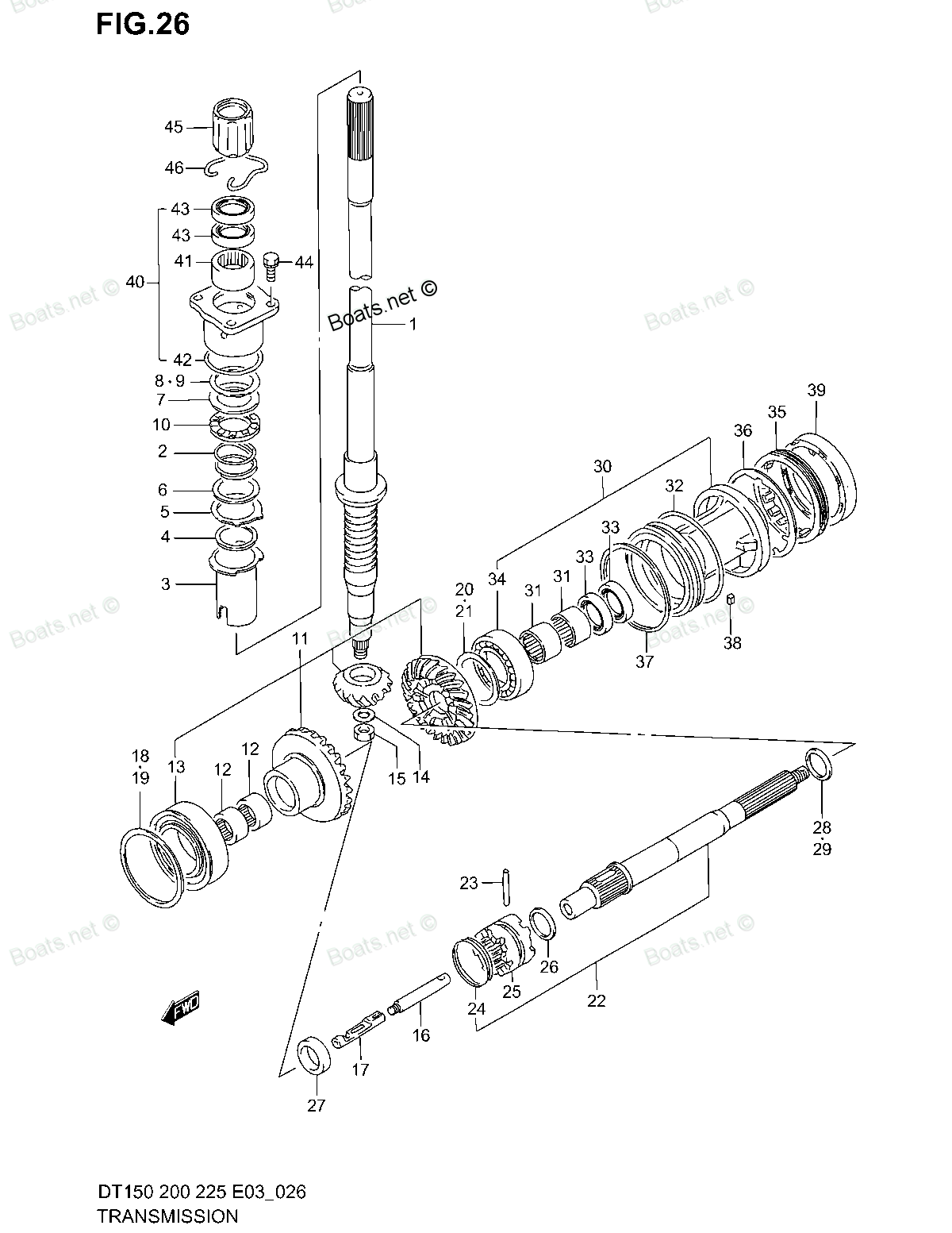
09160-00001 SPACER Suzuki
DT150, DT150SSH, DT150SSJ, DT150SSK, DT150SSL, DT150SSM, DT150SSN, DT150STCLP, DT150STCLR, DT150STCLS, DT150STCLT, DT150TCLH, DT150TCLJ, DT150TCLK, DT150TCLL, DT150TCLM, DT150TCLN, DT150TCLP, DT150TCLR, DT150TCXGM, DT150TCXGN, DT150TCXGP, DT150TCXGR,
SPACER

Price: query
Rating:
Number on catalog scheme: 37
Compatible models:
DT150
DT150SSH
DT150SSJ
DT150SSK
DT150SSL
DT150SSM
DT150SSN
DT150STCLP
DT150STCLR
DT150STCLS
DT150STCLT
DT150TCLH
DT150TCLJ
DT150TCLK
DT150TCLL
DT150TCLM
DT150TCLN
DT150TCLP
DT150TCLR
DT150TCXGM
DT150TCXGN
DT150TCXGP
DT150TCXGR
DT150TCXGS
DT150TCXGT
DT150TCXH
DT150TCXJ
DT150TCXK
DT150TCXL
DT150TCXM
DT150TCXN
DT150TCXP
DT150TCXR
DT150TCXS
DT150TCXT
DT200
DT225
Suzuki
Suzuki entire parts catalog list:
- TRANSMISSION » 09160-00001
- TRANSMISSION » 09160-00001
- TRANSMISSION » 09160-00001
- TRANSMISSION » 09160-00001
- TRANSMISSION » 09160-00001
- TRANSMISSION » 09160-00001
- TRANSMISSION » 09160-00001
- TRANSMISSION » 09160-00001
- TRANSMISSION » 09160-00001
- TRANSMISSION » 09160-00001
- TRANSMISSION » 09160-00001
- TRANSMISSION » 09160-00001
- TRANSMISSION » 09160-00001
- TRANSMISSION » 09160-00001
- TRANSMISSION » 09160-00001
- TRANSMISSION » 09160-00001
- TRANSMISSION » 09160-00001
- TRANSMISSION » 09160-00001
- TRANSMISSION » 09160-00001
- TRANSMISSION » 09160-00001
- TRANSMISSION » 09160-00001
- TRANSMISSION » 09160-00001
- TRANSMISSION » 09160-00001
- TRANSMISSION » 09160-00001
- TRANSMISSION » 09160-00001
- TRANSMISSION » 09160-00001
- TRANSMISSION » 09160-00001
- TRANSMISSION » 09160-00001
- TRANSMISSION » 09160-00001
- TRANSMISSION » 09160-00001
- TRANSMISSION » 09160-00001
- TRANSMISSION » 09160-00001
- TRANSMISSION » 09160-00001
- TRANSMISSION » 09160-00001
- TRANSMISSION » 09160-00001
- TRANSMISSION » 09160-00001
- TRANSMISSION » 09160-00001
Information:
1. Install the camshaft bearings in the fuel injection pump housing with tool (C). Install the bearing in governor end of housing so the lubrication hole in the bearing is in alignment with lubrication hole in housing. Install the camshaft bearings even with outside ends of fuel injection pump housing.
Install the rack bearing in the governor end of the housing with the small holes in the bearing parallel to the vertical centerline in the pump.
2. Install the rack bearing in the governor end of the housing with tooling (F). Install the bearing so it will be .195 .005 in. (4.95 0.13 mm) lower than the face of the housing. Tooling (D) must be used to install the rack bearing in the accessory drive end of the housing. This will put the tab for the bearing in its correct position and install the bearing to the correct depth. 3. Put clean engine oil on camshaft. Install the camshaft in fuel injection pump housing. 4. Put the governor drive gear (1) and spring (2) in position on the camshaft. Install the camshaft plate (3), bolt and lock. 5. Install lifters (4) in their correct positions in the housing. Put clean engine oil on the rack. Install rack (5) in the fuel injection pump housing with the opening in the rack near the governor end of the housing.6. Install the spacers in their respective positions in the housing. When new lifters and pumps are installed, it is necessary to make adjustment of the fuel pump timing. See FUEL INJECTION PUMP TIMING DIMENSIONS SETTING, OFF ENGINE in TESTING AND ADJUSTING.7. Assemble the fuel injection pumps as follows: a) Put clean fuel oil on all parts.b) Install the spring on the barrel.c) Install the washer on the plunger and gear segment. Install the plunger in the barrel.d) Install the spring and check valve in the bonnet.e) Put the bonnet in position on the barrel and install the ring to hold the unit together.f) Install the seal on the bonnet.
Make sure the fuel rack is in the center (zero) position before the fuel injection pumps are installed.
8. Put the rack in the center position with tooling (E) as follows: a) Install location fixture (6) on the fuel injection pump housing.b) Install the gauge (7). Move the gauge (7) to zero. Push the rack (5) against the gauge.c) Install the clamp (8) on pump housing as illustrated. This will keep the rack in the center when the fuel injection pumps are installed. 9. With the rack in the center, install the fuel injection pumps as follows: a) Turn the camshaft until the lobe of the camshaft is down for the pump to be installed.b) Install tool (B) on the pump.c) Put the grooves (9) in the bonnet and barrel in alignment with the groove (10) in the pump gear segment. Put the pump in position so the grooves are in alignment with the guide pins in the housing bore. Install the pump in its correct position in the housing. d) Install bushing (11) over the bonnet. Install tool (B) on the bonnet and push down on tool (B). Tighten bushing (11) by hand until the bushing is even with top of housing. If installation of the bushing can not be made this far by hand, remove it. Remove the pump, put the parts in alignment again and install the bushing again. Tighten bushing (11) to a torque of 140 to 160 lb.ft. (190 219 N m).
If installation of pump is correct, the bushing can be tightened by hand until it is even with face of pump housing.
e) Make a check of the rack travel after each pump is installed as follows: Move clamp (8) away from the end of the rack. Use gauge (7) to measure the rack movement. The total rack movement must be .800 in. (20.32 mm). If the rack can not be moved this distance, the pump gear segment is not in the correct position and the pump must be removed and installed again. f) Remove tool (B) and tool (E). Install tool (A) and tighten the bushing to a torque of 150 10 lb.ft. (205 14 N m). Remove tool (A). Install the washers and protection caps for the fuel injection pumps.end by:a) connection of governor to fuel injection pump housingb) install fuel injection pump housing and governorc) adjust governor and set the rack (See GOVERNOR ADJUSTMENTS and FUEL RACK SETTING in TESTING AND ADJUSTING)
Parts spacer Suzuki:
09180-06248

09180-06248 SPACER, CHOKE SOLENOID
DT115, DT140, DT150, DT150SSH, DT150SSJ, DT150SSK, DT150SSL, DT150SSM, DT150SSN, DT150STCLP, DT150STCLR, DT150STCLS, DT150STCLT, DT150TCLH, DT150TCLJ, DT150TCLK, DT150TCLL, DT150TCLM, DT150TCLN, DT150TCLP, DT150TCLR, DT150TCXGM, DT150TCXGN, DT150TCXG
09180-06095

09180-06095 SPACER
DT150, DT150SSH, DT150SSJ, DT150SSK, DT150SSL, DT150SSM, DT150SSN, DT150STCLP, DT150STCLR, DT150STCLS, DT150STCLT, DT150TCLH, DT150TCLJ, DT150TCLK, DT150TCLL, DT150TCLM, DT150TCLN, DT150TCLP, DT150TCLR, DT150TCXGM, DT150TCXGN, DT150TCXGP, DT150TCXGR,
09180-05031
09180-05031 SPACER
DT150SSH, DT150SSJ, DT150SSK, DT150SSL, DT150SSM, DT150SSN, DT150STCLP, DT150STCLR, DT150STCLS, DT150STCLT, DT150TCLH, DT150TCLJ, DT150TCLK, DT150TCLL, DT150TCLM, DT150TCLN, DT150TCLP, DT150TCLR, DT150TCXGM, DT150TCXGN, DT150TCXGP, DT150TCXGR, DT150T
09180-05036
09180-05036 SPACER
DT150SSH, DT150SSJ, DT150SSK, DT150SSL, DT150SSM, DT150SSN, DT150STCLP, DT150STCLR, DT150STCLS, DT150STCLT, DT150TCLH, DT150TCLJ, DT150TCLK, DT150TCLL, DT150TCLM, DT150TCLN, DT150TCLP, DT150TCLR, DT150TCXGM, DT150TCXGN, DT150TCXGP, DT150TCXGR, DT150T
09180-06223
09180-06223 SPACER
DT150, DT150SSH, DT150SSJ, DT150SSK, DT150SSL, DT150SSM, DT150SSN, DT150STCLP, DT150STCLR, DT150STCLS, DT150STCLT, DT150TCLH, DT150TCLJ, DT150TCLK, DT150TCLL, DT150TCLM, DT150TCLN, DT150TCLP, DT150TCLR, DT150TCXGM, DT150TCXGN, DT150TCXGP, DT150TCXGR,
09180-06294

09180-06294 SPACER
DT150, DT150SSH, DT150SSJ, DT150SSK, DT150SSL, DT150SSM, DT150SSN, DT150STCLP, DT150STCLR, DT150STCLS, DT150STCLT, DT150TCLH, DT150TCLJ, DT150TCLK, DT150TCLL, DT150TCLM, DT150TCLN, DT150TCLP, DT150TCLR, DT150TCXGM, DT150TCXGN, DT150TCXGP, DT150TCXGR,
09180-06120

09180-06120 SPACER
DT150SSH, DT150SSJ, DT150SSK, DT150SSL, DT150SSM, DT150SSN, DT150STCLP, DT150STCLR, DT150STCLS, DT150STCLT, DT150TCLH, DT150TCLJ, DT150TCLK, DT150TCLL, DT150TCLM, DT150TCLN, DT150TCLP, DT150TCLR, DT150TCXGM, DT150TCXGN, DT150TCXGP, DT150TCXGR, DT150T
09180-08211