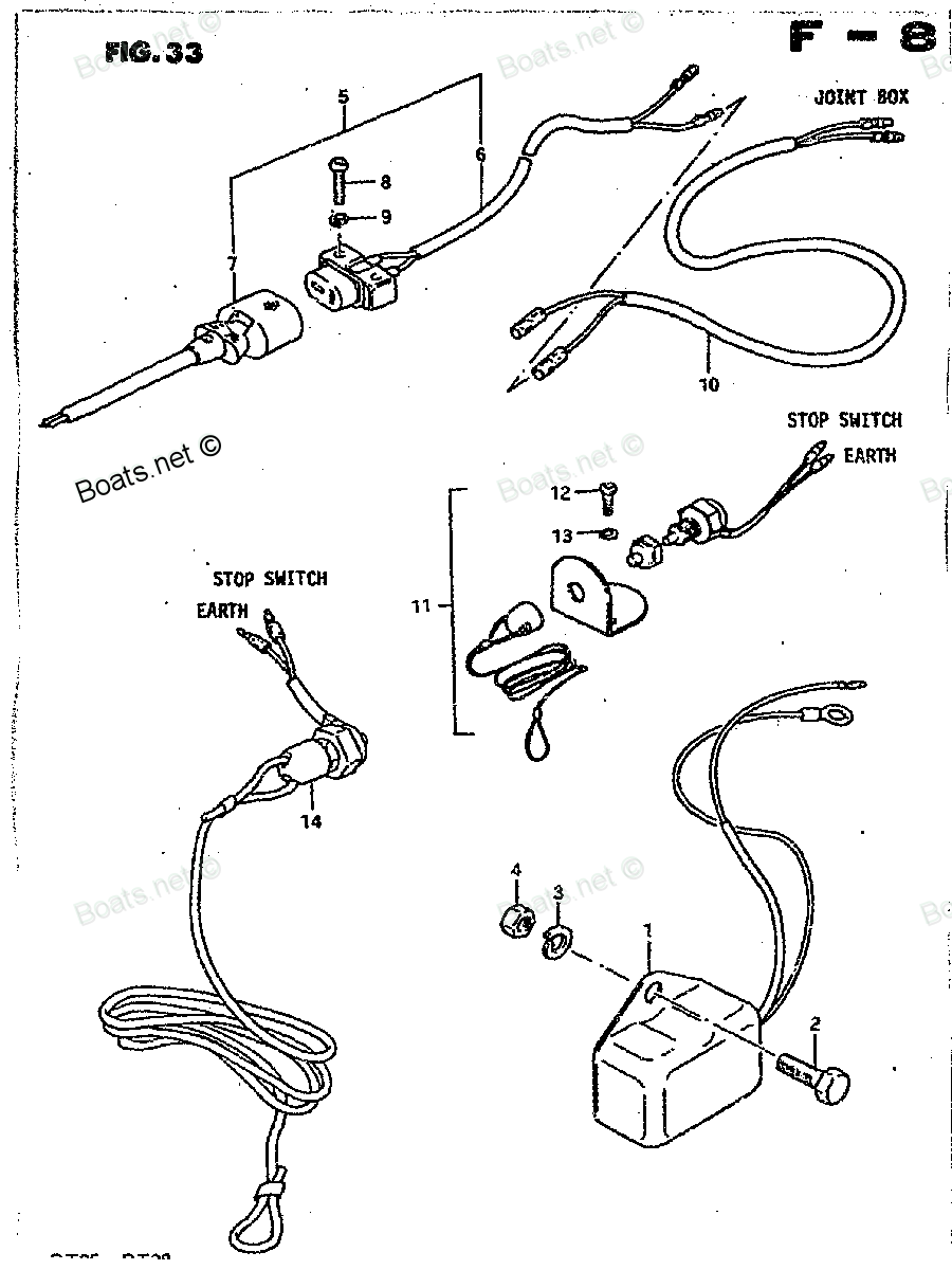
37802-98300 Switch Set, Emergency Suzuki
25ELT, 25ELX, DT15 MLE, DT15ELD, DT15ELE, DT15ELF, DT15ESD, DT15ESE, DT15ESF, DT15MLD, DT15MLF, DT15MSD, DT15MSE, DT15MSF, DT16LT, DT16LT, DT16LT, DT16ST, DT16ST, DT16ST, DT25ELZ, DT25EST, DT25ESX, DT25ESZ, DT25MLT, DT25MLX, DT25MLZ, DT25MST, DT25MSX
Switch

Price: query
Rating:
Number on catalog scheme: 11-2
Compatible models:
25ELT
25ELX
DT15 MLE
DT15ELD
DT15ELE
DT15ELF
DT15ESD
DT15ESE
DT15ESF
DT15MLD
DT15MLF
DT15MSD
DT15MSE
DT15MSF
DT16LT
DT16ST
DT25ELZ
DT25EST
DT25ESX
DT25ESZ
DT25MLT
DT25MLX
DT25MLZ
DT25MST
DT25MSX
DT25MSZ
DT28G
DT28J
DT28Z
DT3.5LD
DT3.5LE
DT3.5LT
DT3.5LX
DT3.5LZ
DT3.5SD
DT3.5SE
DT3.5ST
DT3.5SX
DT3.5SZ
DT5LT
DT5LX
DT5LZ
DT5ST
DT5SX
DT5SZ
DT6LE
DT6LF
DT6SE
DT6SF
DT8LD
DT8LE
DT8LF
DT8LT
DT8LX
DT8LZ
DT8SD
DT8SE
DT8SF
DT8ST
DT8SX
DT8SZ
DT9.9ELD
DT9.9ELE
DT9.9ELF
DT9.9ESD
DT9.9ESE
DT9.9ESF
DT9.9LT
DT9.9LX
DT9.9LZ
DT9.9MLD
DT9.9MLE
DT9.9MLF
DT9.9MSD
DT9.9MSE
DT9.9MSF
DT9.9ST
DT9.9SX
DT9.9SZ
Suzuki
Suzuki entire parts catalog list:
- Optional Regulator » 37802-98300
- Optional Regulator » 37802-98300
- Optional Electrical 3 » 37802-98300
- Optional Electrical 3 » 37802-98300
- Optional Electrical 3 » 37802-98300
- Optional Electrical 3 » 37802-98300
- Optional Electrical 3 » 37802-98300
- Optional Electrical 3 » 37802-98300
- Optional Electrical 3 » 37802-98300
- Optional Electrical 3 » 37802-98300
- Optional Electrical 3 » 37802-98300
- Optional Electrical 3 » 37802-98300
- Optional Electrical 3 » 37802-98300
- Optional Electrical 3 » 37802-98300
- Optional-Electrical 2 » 37802-98300
- Optional-Electrical 2 » 37802-98300
- Optional-Electrical 2 » 37802-98300
- Optional-Electrical 2 » 37802-98300
- Optional-Electrical 2 » 37802-98300
- Optional-Electrical 2 » 37802-98300
- Optional Regulator » 37802-98300
- Optional Regulator » 37802-98300
- Optional Regulator » 37802-98300
- Optional Regulator » 37802-98300
- Optional Regulator » 37802-98300
- Optional Regulator » 37802-98300
- Optional Regulator » 37802-98300
- Optional Regulator » 37802-98300
- Optional Regulator » 37802-98300
- Optional Regulator » 37802-98300
- Optional Regulator » 37802-98300
- Optional Regulator » 37802-98300
- Optional Regulator » 37802-98300
- Optional Electrical » 37802-98300
- Optional Electrical » 37802-98300
- Optional Electrical » 37802-98300
- Optional Electrical » 37802-98300
- Optional Electrical » 37802-98300
- Optional Electrical » 37802-98300
- Optional Electrical » 37802-98300
- Optional Electrical » 37802-98300
- Optional Electrical » 37802-98300
- Optional Electrical » 37802-98300
- Optional Electrical » 37802-98300
- Optional Electrical » 37802-98300
- Optional Electrical » 37802-98300
- Optional Electrical » 37802-98300
- Optional Electrical » 37802-98300
- Optional Electrical » 37802-98300
- Optional Electrical » 37802-98300
- Optional Electrical » 37802-98300
- Optional Electrical » 37802-98300
- Optional Electrical » 37802-98300
- Optional Electrical » 37802-98300
- Optional Electrical » 37802-98300
- Optional Electrical » 37802-98300
- Optional Electric » 37802-98300
- Optional Electric » 37802-98300
- Optional Electric » 37802-98300
- Optional Electrical » 37802-98300
- Optional Electrical » 37802-98300
- Optional Electrical » 37802-98300
- Optional Electric » 37802-98300
- Optional Electric » 37802-98300
- Optional Electric » 37802-98300
- Optional Electrical 3 » 37802-98300
- Optional Electrical 3 » 37802-98300
- Optional Electrical 3 » 37802-98300
- Optional Electrical 3 » 37802-98300
- Optional Electrical 3 » 37802-98300
- Optional Electrical 3 » 37802-98300
- Optional Electrical 2 » 37802-98300
- Optional Electrical 2 » 37802-98300
- Optional Electrical 2 » 37802-98300
- Optional Electrical 3 » 37802-98300
- Optional Electrical 3 » 37802-98300
- Optional Electrical 3 » 37802-98300
- Optional Electrical 3 » 37802-98300
- Optional Electrical 3 » 37802-98300
- Optional Electrical 3 » 37802-98300
- Optional Electrical 2 » 37802-98300
- Optional Electrical 2 » 37802-98300
- Optional Electrical 2 » 37802-98300
Information:
Table 1
Diagnostic Codes Table
J1939 Code and Description Conditions which Generate this Code System Response
639-9
J1939 Network #1 : Abnormal Update Rate Communication issue on the Global data link between the generator and the ISM. One module is no longer broadcasting. The code is logged.
1231-9
J1939 Network #2 : Abnormal Update Rate Communication issue with the fuel valve and the ISM on the CAN data link. The code is logged.
1231-14
J1939 Network #2 : Special Instruction All communications on the data link have been lost. All communications on the data link have been lost.
2241-9
Source Address 241 : Abnormal Update Rate The engine ECM is not communicating with the ISM. All communications on the data link have been lost.
2452-9
Generator Total Real Power : Abnormal Update Rate Communication issue on the Global data link between the ECM and the EMCP. One module is no longer broadcasting. The code is logged.
Gas substitution shuts off. Use this procedure to troubleshoot the electrical system if a problem is suspected with the CAN data link or the Cat Data Link.Note: This procedure checks for an open or for a short in the data link circuits.If Caterpillar Electronic Technician (ET) will not communicate with the ECM, refer to Troubleshooting, "Electronic Service Tool Does Not Communicate" before you begin this procedure. The procedure will verify that electrical power is being supplied to the ECM and to the service tool connector.The data links are used to communicate information between the engine ECM and other control modules that are a part of the application. Cat ET also communicates with the ECM via the data links.The service tool connector contains connections for electrical power and for the data links.When the keyswitch is in the OFF position, Cat ET may communicate with the ECM. However, the communications may be disrupted and the communications may require frequent reconnection. In order to avoid this problem, place the keyswitch in the ON position when Cat ET is being used.Cat ET may display the following error message:"The version of the ECM is not recognized and the integrity of the changed parameters and displayed data is not guaranteed."This message indicates one of the following conditions:
The flash file in the ECM is newer than the version of Cat ET.
The latest version of Cat ET has not been installed.
Illustration 1 g03376968
Illustration 2 g01444702
Terminal locations at the service tool connector
(A) +Battery
(B) −Battery
(C) CAN data link global shield
(D) Cat Data Link +
(E) Cat Data Link −
(F) CAN data link global −
(G) CAN data link global +
Illustration 3 g03321103
Terminal locations at the P1 ECM connector that are for the data links
(P1-8) Cat Data Link +
(P1-9) Cat Data Link −
(P1-34) Global CAN data link −
(P1-42) Global CAN shield
(P1-50) Global CAN data link +
(P1-52) +Battery
(P1-53) +Battery
(P1-55) +Battery
(P1-57) +Battery
(P1-61) −Battery
(P1-63) −Battery
(P1-65) −Battery
(P1-67) −Battery
(P1-69) −Battery
(P1-70) Keyswitch
Illustration 4 g01326307
Terminal locations at the P2 ECM connector that are for the data link
(P2-11) Local CAN data link −
(P2-12) Local CAN data link +
(P2-23) Local CAN shield
Illustration 5 g03325860
Terminal locations at the P1 ISM connector that are for the data link
(P1-48) Global CAN data link −
(P1-49) Global CAN shield
(P1-50) Global CAN data link +
(P1-51) Local CAN data link −
(P1-52) Local CAN shield
(P1-61) Local CAN data link +
(P1-66) −Battery
(P1-67) −Battery
(P1-68) + Battery
(P1-69) + Battery
(P1-70) Keyswitch
Illustration 6 g01355248
Terminal locations at the termination resistors
(A) CAN data link +
(B) CAN data link −
(C) Shield
Table 2
Troubleshooting Test Steps Values Results
1. Inspect the Electrical Connectors and the Wiring
Note: Carefully follow this procedure in order to identify an intermittent problem.
A. Perform a visual inspection of the wiring between the P1 and P2 ECM connectors, P1 and P2 ISM connectors, the termination resistors, and the service tool connector. Also, inspect the wiring and the connectors at various controllers and control boxes.
Look for these problems:
- Harness damage that is caused by chafing
- Harness damage that is caused by excessive heat
- Look for moisture on the wiring and in the connectors.
- Pull on the wires that are associated with the data links.
This test verifies that the wire is properly crimped to the terminal and that the terminal is properly inserted into the connector.
Connectors
Result: The wiring and the connectors appear to be OK.
Proceed to Test Step 2
Result: There is a problem with the wiring or with a connector.
Repair: the connectors or wiring and/or replace the connectors or wiring. Ensure that all of the connector seals are properly in place and ensure that the connectors are coupled.
Verify that the repair eliminates the problem.
2. Bypass the Wiring for the Data Link
A. Connect the 217-0113 Wiring Harness (ECM BYPASS) to the J1 connector, to the 332-7381 Data Link Cable As, and to the battery.
B. Restore the electrical power to the ECM.
C. Try to establish communication between Cat ET and the ECM.
Data Link
Result: Cat ET and the ECM communicate.
Parts switch Suzuki:
37800-93812
37800-93812 Switch Set, Emergency
20ELB, 20ELC, 20ELN, 25ELB, 25ELC, 25ELN, DT14C, DT14D, DT14F, DT20ESB, DT20ESC, DT20ESN, DT20MLB, DT20MLC, DT20MLN, DT20MSB, DT20MSC, DT20MSN, DT25ESB, DT25ESC, DT25ESN, DT25MLB, DT25MLC, DT25MLN, DT25MSB, DT25MSC, DT25MSN, DT28F, DT2B, DT2C, DT2N,
37800-93813

37800-93813 Switch Set, Emergency
25ELT, 25ELX, DT16LT, DT16LT, DT16LT, DT16ST, DT16ST, DT16ST, DT25ELZ, DT25EST, DT25ESX, DT25ESZ, DT25MLT, DT25MLX, DT25MLZ, DT25MST, DT25MSX, DT25MSZ, DT28G, DT28J, DT28Z, DT2B, DT2C, DT2N, DT3.5LN, DT3.5LT, DT3.5LX, DT3.5LZ, DT3.5SN, DT3.5ST, DT3.5
37800-93150
37800-93150 Switch Assembly, Engine Stop
DT14D, DT14F, DT16LC, DT16LN, DT16SC, DT16SN, DT3.5LD, DT3.5LE, DT3.5LN, DT3.5LT, DT3.5LX, DT3.5LZ, DT3.5SD, DT3.5SE, DT3.5SN, DT3.5ST, DT3.5SX, DT3.5SZ, DT50, DT50, DT50M, DT50W, DT5LD, DT5LT, DT5LX, DT5LZ, DT5SD, DT5ST, DT5SX, DT5SZ, DT65, DT65, DT
37110-93301
37110-93301 Switch Assembly, ignition
20ELB, 20ELC, 20ELN, 25ELB, 25ELC, 25ELN, 25ELT, 25ELX, DT20ESB, DT20ESC, DT20ESN, DT20MLB, DT20MLC, DT20MLN, DT20MSB, DT20MSC, DT20MSN, DT25ELZ, DT25ESB, DT25ESC, DT25ESN, DT25EST, DT25ESX, DT25ESZ, DT25MLB, DT25MLC, DT25MLN, DT25MLT, DT25MLX, DT25M
37721-95251
37721-95251 Switch Assembly, neutral
25ELB, 25ELC, 25ELN, 25ELT, DT25ESB, DT25ESC, DT25ESN, DT25EST, DT25MLB, DT25MLC, DT25MLN, DT25MLT, DT25MSB, DT25MSC, DT25MSN, DT25MST, DT28F, DT28G, DT35ELT, DT35ELX, DT35ELZ, DT35EST, DT35ESX, DT35ESZ, DT35MLT, DT35MLX, DT35MLZ, DT35MST, DT35MSX, D
37820-95201
37820-95201 Switch Assembly, emergency
25ELT, 25ELX, DT16LT, DT16LT, DT16LT, DT16ST, DT16ST, DT16ST, DT25ELZ, DT25EST, DT25ESX, DT25ESZ, DT25MLT, DT25MLX, DT25MLZ, DT25MST, DT25MSX, DT25MSZ, DT28G, DT28J, DT28Z, DT35ELT, DT35ELX, DT35ELZ, DT35EST, DT35ESX, DT35ESZ, DT35MLT, DT35MLX, DT35M
37721-93900
37721-93900 Switch Assembly, Neutral
DT15 MLE, DT15ELD, DT15ELE, DT15ELF, DT15ESD, DT15ESE, DT15ESF, DT15MLD, DT15MLF, DT15MSD, DT15MSE, DT15MSF, DT9.9ELD, DT9.9ELE, DT9.9ELF, DT9.9ESD, DT9.9ESE, DT9.9ESF, DT9.9MLD, DT9.9MLE, DT9.9MLF, DT9.9MSD, DT9.9MSE, DT9.9MSF
37721-93901
37721-93901 Switch Assembly, Neutral
DT15 MLE, DT15ELD, DT15ELE, DT15ELF, DT15ESD, DT15ESE, DT15ESF, DT15MLD, DT15MLF, DT15MSD, DT15MSE, DT15MSF, DT9.9ELD, DT9.9ELE, DT9.9ELF, DT9.9ESD, DT9.9ESE, DT9.9ESF, DT9.9MLD, DT9.9MLE, DT9.9MLF, DT9.9MSD, DT9.9MSE, DT9.9MSF