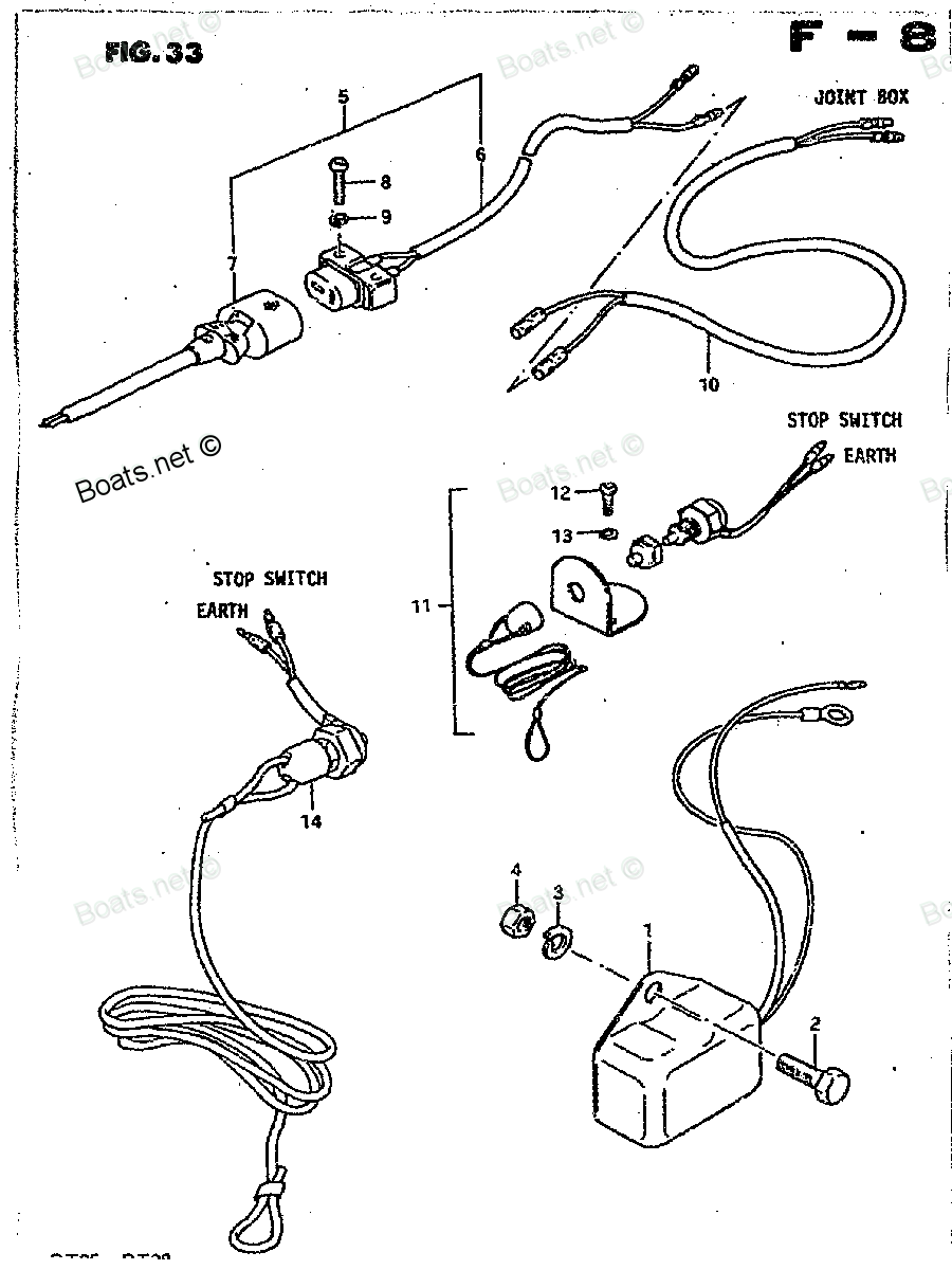
37820-95201 Switch Assembly, emergency Suzuki
25ELT, 25ELX, DT16LT, DT16LT, DT16LT, DT16ST, DT16ST, DT16ST, DT25ELZ, DT25EST, DT25ESX, DT25ESZ, DT25MLT, DT25MLX, DT25MLZ, DT25MST, DT25MSX, DT25MSZ, DT28G, DT28J, DT28Z, DT35ELT, DT35ELX, DT35ELZ, DT35EST, DT35ESX, DT35ESZ, DT35MLT, DT35MLX, DT35M
Switch

Price: query
Rating:
Number on catalog scheme: 14-2
Compatible models:
25ELT
25ELX
DT16LT
DT16ST
DT25ELZ
DT25EST
DT25ESX
DT25ESZ
DT25MLT
DT25MLX
DT25MLZ
DT25MST
DT25MSX
DT25MSZ
DT28G
DT28J
DT28Z
DT35ELT
DT35ELX
DT35ELZ
DT35EST
DT35ESX
DT35ESZ
DT35MLT
DT35MLX
DT35MLZ
DT35MST
DT35MSX
DT35MSZ
DT40ELT
DT40ELX
DT40ELZ
DT40EST
DT40ESX
DT40ESZ
DT40MLT
DT40MLX
DT40MLZ
DT40MSX
DT40MSZ
DT50
DT50ELB
DT50ELC
DT50ELN
DT50ESB
DT50ESC
DT50ESN
DT50M
DT50MLC
DT50MLN
DT50MSC
DT50MSN
DT50W
DT60CLD
DT60CLE
DT65
DT65ELC
DT65ELN
DT65ESC
DT65ESN
Suzuki
Suzuki entire parts catalog list:
- Optional Regulator » 37820-95201
- Optional Remote Control 3 » 37820-95201
- Optional Regulator » 37820-95201
- Optional Remote Control 3 » 37820-95201
- Optional-Remote Control 3 » 37820-95201
- Optional-Remote Control 3 » 37820-95201
- Optional-Remote Control 3 » 37820-95201
- Optional-Remote Control 3 » 37820-95201
- Optional-Remote Control 3 » 37820-95201
- Optional-Remote Control 3 » 37820-95201
- Optional Remote Control 3 » 37820-95201
- Optional Regulator » 37820-95201
- Optional Regulator » 37820-95201
- Optional Remote Control 3 » 37820-95201
- Optional Regulator » 37820-95201
- Optional Remote Control 3 » 37820-95201
- Optional Regulator » 37820-95201
- Optional Remote Control 3 » 37820-95201
- Optional Regulator » 37820-95201
- Optional Remote Control 3 » 37820-95201
- Optional Remote Control 3 » 37820-95201
- Optional Regulator » 37820-95201
- Optional Regulator » 37820-95201
- Optional Remote Control 3 » 37820-95201
- Optional Regulator » 37820-95201
- Optional Remote Control 3 » 37820-95201
- Optional Regulator » 37820-95201
- Optional Remote Control 3 » 37820-95201
- Optional Remote Control 3 » 37820-95201
- Optional Regulator » 37820-95201
- Optional Remote Control 3 » 37820-95201
- Optional Regulator » 37820-95201
- Optional Regulator » 37820-95201
- Optional Remote Control 3 » 37820-95201
- Optional Regulator » 37820-95201
- Optional Remote Control 3 » 37820-95201
- Remote Control 1 » 37820-95201
- Remote Control 1 » 37820-95201
- Remote Control 1 » 37820-95201
- Remote Control 1 » 37820-95201
- Remote Control 1 » 37820-95201
- Remote Control 1 » 37820-95201
- Remote Control 1 » 37820-95201
- Remote Control 1 » 37820-95201
- Remote Control 1 » 37820-95201
- Remote Control 1 » 37820-95201
- Remote Control 1 » 37820-95201
- Remote Control 1 » 37820-95201
- Remote Control 1 » 37820-95201
- Remote Control 1 » 37820-95201
- Remote Control 1 » 37820-95201
- Remote Control 1 » 37820-95201
- Remote Control 1 » 37820-95201
- Remote Control 1 » 37820-95201
- Remote Control 1 » 37820-95201
- Remote Control 1 » 37820-95201
- Remote Control 1 » 37820-95201
- Remote Control 1 » 37820-95201
- Remote Control 1 » 37820-95201
- REMOTE CONTROL (1) » 37820-95201
- Remote Control 1 » 37820-95201
- Remote Control 1 » 37820-95201
- Remote Control 1 » 37820-95201
- Remote Control 1 » 37820-95201
- Remote Control 1 » 37820-95201
- Remote Control 1 » 37820-95201
- REMOTE CONTROL (1) » 37820-95201
- Remote Control 1 » 37820-95201
- Remote Control 1 » 37820-95201
- Remote Control 1 » 37820-95201
- Remote Control 1 » 37820-95201
- REMOTE CONTROL (1) » 37820-95201
- Remote Control Box » 37820-95201
- Remote Control Box » 37820-95201
- REMOTE CONTROL (1) » 37820-95201
- REMOTE CONTROL (1) » 37820-95201
- Remote Control 1 » 37820-95201
- Remote Control 1 » 37820-95201
- Remote Control 1 » 37820-95201
- Remote Control 1 » 37820-95201
Information:
Table 1
Required Tools
Tool Part Number Part Description Qty
A 9U-7336 Housing 1
5P-7305 Engine Turning Tool 1
B 230-6284 Timing Pin (Camshaft) 1
C 364-9107 Timing Pin
(Fuel Injection Pump) 1
D 136-4632 Timing Pin (Crankshaft) 1
268-1966 Adapter 1
E 298-5564 T40Torx Socket 1 Start By:
Remove the front cover. Refer to Disassembly and Assembly, "Front Cover - Remove and Install" for the correct procedure.
Remove the valve mechanism cover. Refer to Disassembly and Assembly, "Valve Mechanism Cover - Remove and Install" for the correct procedure.
Keep all parts clean from contaminants.Contaminants may cause rapid wear and shortened component life.
Care must be taken to ensure that fluids are contained during performance of inspection, maintenance, testing, adjusting and repair of the product. Be prepared to collect the fluid with suitable containers before opening any compartment or disassembling any component containing fluids.Dispose of all fluids according to local regulations and mandates.
Note: Care must be taken in order to ensure that the fuel injection pump timing is not lost during the removal of the front gear group. Carefully follow the procedure in order to remove the gear group.
If the air compressor is equipped with a hydraulic pump, remove the hydraulic pump. Refer to Original Equipment Manufactures (OEM) for the correct procedure.
If the engine is equipped with an air compressor, remove the air compressor. Refer to Disassembly and Assembly, "Air Compressor - Remove" for the correct procedure.
If the engine is equipped with only a hydraulic pump, remove the hydraulic pump. Refer to OEM for the correct procedure.
Use Tooling (A) in order to rotate the crankshaft so that number one piston is at top dead center on the compression stroke. Refer to System Operation, Testing and Adjusting, "Finding Top Center Position for No.1 Piston" for the correct procedure. Note: Do not use excessive force to install Tooling (D). Do not use Tooling (D) to hold the crankshaft during repairs.
Illustration 1 g02486477
Remove plug (1) from the cylinder block. Remove O-ring seal (2) from the plug.
Use Tooling (A) in order to rotate the crankshaft so that number one piston is at top dead center on the compression stroke. Refer to System Operation, Testing and Adjusting, "Finding Top Center Position for No.1 Piston" for the correct procedure. Install Tooling (D) through Hole (W) in order to lock the crankshaft so that number one piston is at top dead center on the compression stroke.
Remove Tooling (D).
Use Tooling (A) in order to rotate the crankshaft in a clockwise direction and position the crankshaft at the safe position. Refer to System Operation, Testing and Adjusting, "Position the Valve Mechanism Before Maintenance Procedures" for the correct procedure.
Illustration 2 g02048655
Use Tooling (E) in order to loosen threaded inserts (4) on all rocker arms (3). Unscrew threaded inserts (4) on all rocker arms (3) until all valves are fully closed. Ensure that the guides (5) for the pushrods are left in position on the threaded inserts (4). Note: Ensure that ALL threaded inserts are fully unscrewed.
Use Tooling (A) in order to rotate the crankshaft so that number one piston is at top dead center on the compression stroke. Refer to System Operation, Testing and Adjusting, "Finding Top Center Position for No.1 Piston" for the correct procedure. Install Tooling (D) through Hole (W) in order to lock the crankshaft so that number one piston is at top dead center on the compression stroke. Refer to Illustration 1.
Illustration 3 g02488136
Install Tooling (B) through Hole (X) in camshaft gear (6) into the front housing. Use Tooling (B) in order to lock the camshaft in the correct position. Refer to System Operation, Testing and Adjusting, "Finding Top Center Position for No.1 Piston" for the correct procedure.
Use Tooling (C) in order to lock the fuel injection pump gear in the correct position. Refer to Disassembly and Assembly, "Fuel Injection Pump - Remove" for the correct procedure.
Illustration 4 g02052394
If the right-hand side of the engine is equipped with a hydraulic pump, remove the hydraulic pump. Refer to OEM for the correct procedure.
If necessary, remove bolts (7) from plate (8). Remove plate (8) and remove O-ring seal (9).
Remove circlip (10) and remove gear assembly (11) from front housing (12).
Illustration 5 g02053673
If necessary, follow Step 16.a through Step 16.b in order to disassemble gear assembly (11).
Remove circlip (13) from gear assembly (11).
Place gear assembly (11) on a suitable support. Press bearing (14) from gear (15).
Parts switch Suzuki:
37800-93813

37800-93813 Switch Set, Emergency
25ELT, 25ELX, DT16LT, DT16LT, DT16LT, DT16ST, DT16ST, DT16ST, DT25ELZ, DT25EST, DT25ESX, DT25ESZ, DT25MLT, DT25MLX, DT25MLZ, DT25MST, DT25MSX, DT25MSZ, DT28G, DT28J, DT28Z, DT2B, DT2C, DT2N, DT3.5LN, DT3.5LT, DT3.5LX, DT3.5LZ, DT3.5SN, DT3.5ST, DT3.5
37110-95250
37110-95250 Switch Assembly, ignition
DT50ELB, DT50ELC, DT50ELN, DT50ESB, DT50ESC, DT50ESN, DT50MLC, DT50MLN, DT50MSC, DT50MSN, DT65ELC, DT65ELN, DT65ESC, DT65ESN
37110-95251
37110-95251 Switch Assembly, ignition
DT35ELT, DT35ELX, DT35ELZ, DT35EST, DT35ESX, DT35ESZ, DT35MLT, DT35MLX, DT35MLZ, DT35MST, DT35MSX, DT35MSZ, DT40ELT, DT40ELX, DT40ELZ, DT40EST, DT40ESX, DT40ESZ, DT40MLT, DT40MLX, DT40MLZ, DT40MSX, DT40MSZ, DT50, DT50ELB, DT50ELC, DT50ELN, DT50ESB, D
37110-95200
37110-95200 Switch Assembly, ignition
DT50ELB, DT50ELC, DT50ELN, DT50ESB, DT50ESC, DT50ESN, DT50MLC, DT50MLN, DT50MSC, DT50MSN, DT65ELC, DT65ELN, DT65ESC, DT65ESN
37110-95351
37110-95351 Switch Assembly, ignition
25ELT, 25ELX, DT16LT, DT16LT, DT16LT, DT16ST, DT16ST, DT16ST, DT25ELZ, DT25EST, DT25ESX, DT25ESZ, DT25MLT, DT25MLX, DT25MLZ, DT25MST, DT25MSX, DT25MSZ, DT28G, DT28J, DT28Z, DT35ELT, DT35ELX, DT35ELZ, DT35EST, DT35ESX, DT35ESZ, DT35MLT, DT35MLX, DT35M
37110-95550
37110-95550 Switch Assembly, ignition
DT35ELT, DT35ELX, DT35ELZ, DT35EST, DT35ESX, DT35ESZ, DT35MLT, DT35MLX, DT35MLZ, DT35MST, DT35MSX, DT35MSZ, DT40ELT, DT40ELX, DT40ELZ, DT40EST, DT40ESX, DT40ESZ, DT40MLT, DT40MLX, DT40MLZ, DT40MSX, DT40MSZ, DT50ELB, DT50ELC, DT50ELN, DT50ESB, DT50ESC
37802-98300
37802-98300 Switch Set, Emergency
25ELT, 25ELX, DT15 MLE, DT15ELD, DT15ELE, DT15ELF, DT15ESD, DT15ESE, DT15ESF, DT15MLD, DT15MLF, DT15MSD, DT15MSE, DT15MSF, DT16LT, DT16LT, DT16LT, DT16ST, DT16ST, DT16ST, DT25ELZ, DT25EST, DT25ESX, DT25ESZ, DT25MLT, DT25MLX, DT25MLZ, DT25MST, DT25MSX
37830-95201