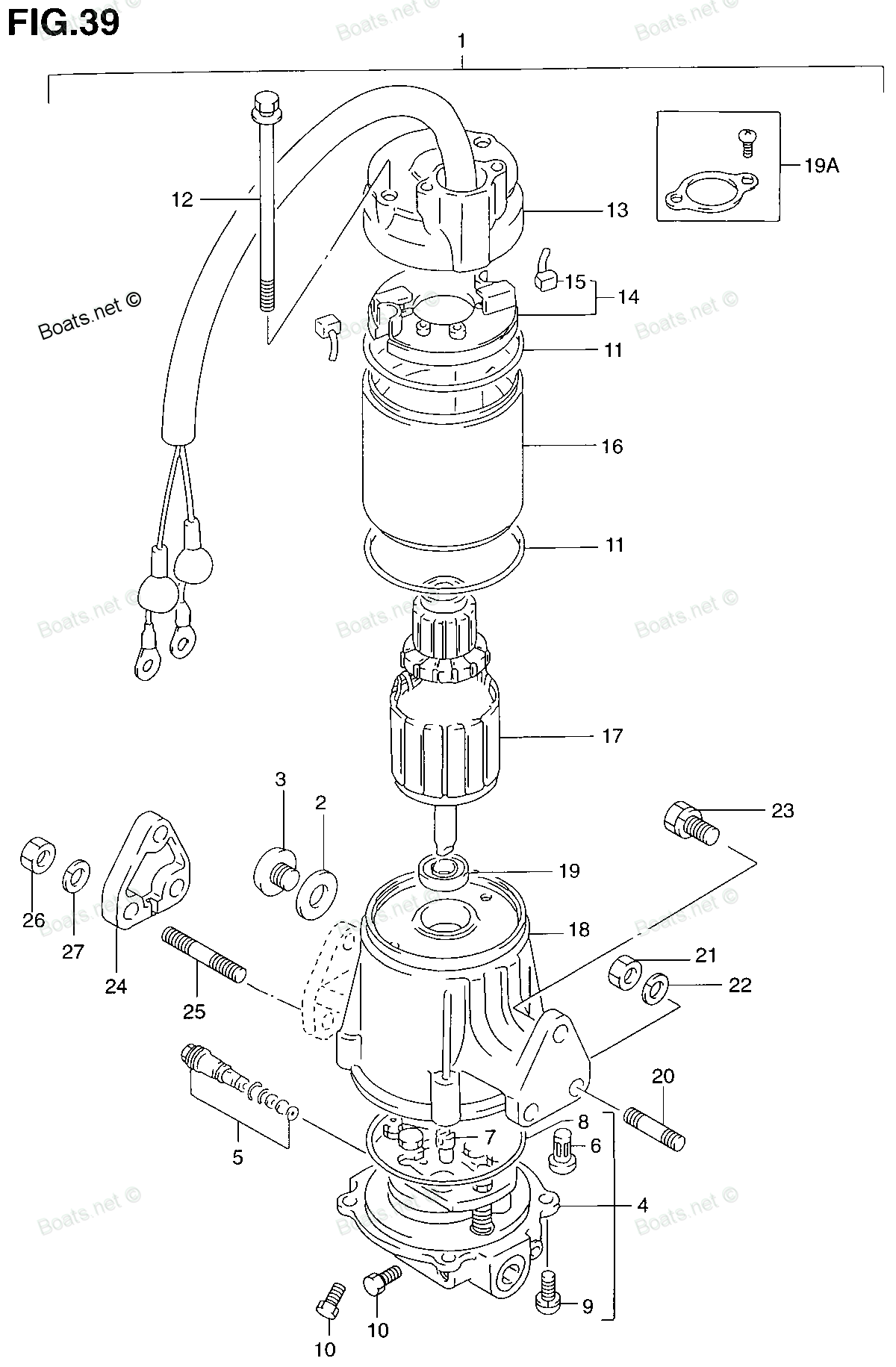
31281-94610 THROUGH BOLT Suzuki
DT115, DT140, DT40C, DT55CRLJ, DT55CRLK, DT55CRLL, DT55HTCLJ, DT55HTCLK, DT55HTCLL, DT55TCLJ, DT55TCLK, DT55TCLL, DT55TCLM, DT55TCLN, DT55TCLP, DT55TCLR, DT55TCLS, DT55TCLT, DT55TCLV, DT65CRLJ, DT65CRLK, DT65CRLL, DT65HTCLK, DT65HTCLL, DT65TCLJ, DT65
THROUGH

Price: query
Rating:
Number on catalog scheme: 12
Compatible models:
DT115
DT140
DT40C
DT55CRLJ
DT55CRLK
DT55CRLL
DT55HTCLJ
DT55HTCLK
DT55HTCLL
DT55TCLJ
DT55TCLK
DT55TCLL
DT55TCLM
DT55TCLN
DT55TCLP
DT55TCLR
DT55TCLS
DT55TCLT
DT55TCLV
DT65CRLJ
DT65CRLK
DT65CRLL
DT65HTCLK
DT65HTCLL
DT65TCLJ
DT65TCLK
DT65TCLL
DT65TCLM
DT65TCLN
DT65TCLP
DT65TCLR
DT65TCLS
DT65TCLT
DT65TCLV
DT75TCLJ
DT75TCLK
DT75TCLL
DT75TCLM
DT75TCLN
DT75TCLP
DT75TCLR
DT75TCLS
DT75TCLT
DT75TCLV
DT85TCLJ
DT85TCLK
DT85TCLL
DT85TCLM
DT85TCLN
DT85TCLP
DT85TCLR
DT85TCLS
DT85TCLT
DT85TCLV
DT85TCLW
DT85TCLX
DT85TCLY
Suzuki
Suzuki entire parts catalog list:
- POWER UNIT (MODEL:90~95) » 31281-94610
- POWER UNIT (MODEL:90~95) » 31281-94610
- POWER UNIT (DT40TC-MODEL:90~93) » 31281-94610
- POWER UNIT 91-94 » 31281-94610
- POWER UNIT 91-94 » 31281-94610
- POWER UNIT 91-94 » 31281-94610
- POWER UNIT 91-94 » 31281-94610
- POWER UNIT 91-94 » 31281-94610
- POWER UNIT 91-94 » 31281-94610
- POWER UNIT 91-94 » 31281-94610
- POWER UNIT 91-94 » 31281-94610
- POWER UNIT 91-94 » 31281-94610
- POWER UNIT 91-94 » 31281-94610
- POWER UNIT 91-94 » 31281-94610
- POWER UNIT 91-94 » 31281-94610
- POWER UNIT 91-94 » 31281-94610
- POWER UNIT 91-94 » 31281-94610
- POWER UNIT 91-94 » 31281-94610
- POWER UNIT 91-94 » 31281-94610
- POWER UNIT 91-94 » 31281-94610
- POWER UNIT 91-94 » 31281-94610
- POWER UNIT 91-94 » 31281-94610
- POWER UNIT 91-94 » 31281-94610
- POWER UNIT 91-94 » 31281-94610
- POWER UNIT 91-94 » 31281-94610
- POWER UNIT 91-94 » 31281-94610
- POWER UNIT 91-94 » 31281-94610
- POWER UNIT 91-94 » 31281-94610
- POWER UNIT 91-94 » 31281-94610
- POWER UNIT 91-94 » 31281-94610
- POWER UNIT 91-94 » 31281-94610
- POWER UNIT 91-94 » 31281-94610
- POWER UNIT 91-94 » 31281-94610
- POWER UNIT 91-94 » 31281-94610
- POWER UNIT 90-94 » 31281-94610
- POWER UNIT 90-94 » 31281-94610
- POWER UNIT 90-94 » 31281-94610
- POWER UNIT 90-94 » 31281-94610
- POWER UNIT 90-94 » 31281-94610
- POWER UNIT 90-94 » 31281-94610
- POWER UNIT 90-94 » 31281-94610
- POWER UNIT 90-94 » 31281-94610
- POWER UNIT 90-94 » 31281-94610
- POWER UNIT 90-94 » 31281-94610
- POWER UNIT 90-94 » 31281-94610
- POWER UNIT 90-94 » 31281-94610
- POWER UNIT 90-94 » 31281-94610
- POWER UNIT 90-94 » 31281-94610
- POWER UNIT 90-94 » 31281-94610
- POWER UNIT 90-94 » 31281-94610
- POWER UNIT 90-94 » 31281-94610
- POWER UNIT 90-94 » 31281-94610
- POWER UNIT 90-94 » 31281-94610
- POWER UNIT 90-94 » 31281-94610
- POWER UNIT 90-94 » 31281-94610
- POWER UNIT 90-94 » 31281-94610
- POWER UNIT 90-94 » 31281-94610
Information:
The fuel system consists of the injection pump assembly (injection pump proper, governor, feed pump, automatic timer), injection nozzle, fuel filter, fuel tank, and other parts.Fuel is fed from the fuel tank through suction hose to the feed pump of the injection pump assembly, and then to the fuel filter, injection pump, and injection nozzle. The excess fuel is returned from the injection nozzle and injection pump to fuel tank.The driving method of the injection pump differs between unit with and without compressor as shown below. When the unit is with an air compressor, the drive gear of the air compressor is driven by the timing gear and between the air compressor crankshaft and autotimer, drive is made by the driving disc. In the case of unit without air compressor, there are two types; the drive gear in the pump drive case is driven by the timing gear and between the coupling in the pump drive case and the auto timer, drive is made by the driving disc; the injection pump drive gear is directly driven by the timing gear.Refer to Group 12 Lubrication for lubrication of the injection pump.(1) Injection Pump Proper Bosch A or AD type injection pump is adopted. The construction of the injection pump is as shown. The injection pump is a device which forces fuel to the injection nozzle and has a mechanism for increasing or decreasing the pressure feed quantity according to the engine load and speed.It has one plunger and delivery valve for each cylinder.The plunger, pushed up by the camshaft and pushed back by the plunger spring, moves up and down through the plunger barrel on a predetermined stroke to feed fuel under pressure.The plunger also controls the injection amount by adjusting the suction/discharge port opening timing. The camshaft is supported by two taper roller bearings and a center bearing. It has two types of cams to operate the actuators and to operate the feed pump-and is driven by the pump drive gear at 1/2 engine speed.(a) Pressure feed of fuel The plunger has an obliquely cut groove (lead) on its side as shown. At the top of the plunger there is a hole which leads to the groove. The plunger barrel has suction/discharge port.The fuel delivered to the injection pump is forced by the rotation of the camshaft or reciprocating motion of the plunger as shown above.When the plunger is at the lowest position or bottom dead center (a), fuel flows through the suction/discharge port into the plunger.Rotation of the camshaft moves the plunger up. When the top surface of the plunger is lined up with the suction/discharge port, application of pressure to fuel begins (b).As the plunger moves up further (c), and the lead of the plunger meets with the suction/discharge port, the high pressure fuel flows through the hole in the plunger and runs back from the lead to the suction/discharge port, and the pressure feed of fuel is completed (d).The plunger stroke during which the fuel is fed under pressure is called the effective stroke.(b) Injection amount control system According to the engine load, the amount of injection is increased or reduced by turning the plunger a certain angle to change the position where the lead meets with the suction discharge port on the up stroke and increasing or reducing the effective stroke. The control rack is coupled to the floating lever in the governor. If the control rack is moved to right or left by operation of the accelerator pedal or governor, the control sleeve in mesh with the rack is turned. Since the bottom of the control sleeve is in mesh with the bar of the plunger, the plunger turns with the control sleeve, so the effective stroke changes and the injection amount increases or decreases. The more the control rack is pulled toward the governor, the less the effective stroke and the less the injection amount.Each plunger is in mesh with this single control rack and simultaneously turns the same amount.(c) Delivery valve The delivery valve, provided on the top of the pump housing, performs the function of discharging the pressure in the injection pump.The fuel compressed to a high pressure by the plunger pushes the delivery valve up and spouts out. If the pressure feed stroke of the plunger ends, the delivery valve is brought back to its original position by the pressure of the delivery valve spring to block the fuel path, thereby preventing counter flow of the fuel.The delivery valve is brought down further until the seat surface is held tight. During that stroke the fuel is drawn back from above to instantly lower the residual pressure between the delivery valve and nozzle. The draw-back effect improves the end break of an injection from the nozzle and prevents after-injection dripping.A delivery valve stopper is provided on the top of the delivery valve spring. The stopper limits the lift of the delivery valve and prevents valve surging during high speed operation. In addition, it reduces the dead volume between the delivery valve and nozzle, thereby stabilizing the injection amount.(d) Overflow valve The overflow valve that stabilizes fuel temperature and velocity distribution in the injection pump for constant injection amount into each cylinder is installed above the pump.The overflow valve is the ball seal type which opens to allow fuel to flow back to the fuel tank when fuel pressure in the pump housing exceeds specified limit.(2) Governor(a) RSV type governorThe RSV type governor is a centrifugal type all-speed governor coupled to the camshaft of the injection pump. The governor not only controls the maximum and minimum speeds but also automatically controls the engine speed at any intermediate speed position. The governor, as shown, consists of flyweights mounted to the injection pump camshaft. When the flyweights turning on the flyweight supporting shaft open outward, the slider mounted to the end of flyweight arm pushes the end of the governor sleeve in the axial direction. The governor sleeve, being made integral with the
Parts through Suzuki:
31281-94510
31281-94510 THROUGH BOLT
DF40, DF40, DF40QH, DF40TL, DF50, DF50, DF50QH, DF50TL, DF60, DF60HL, DF60TL, DF70, DF70THL, DF70TL, DT115, DT140, DT150, DT200, DT225, DT55CLF, DT55CRLG, DT55CRLJ, DT55CRLK, DT55CRLL, DT55CRSG, DT55CRSH, DT55HTCLH, DT55HTCLJ, DT55HTCLK, DT55HTCLL, D
31281-94700
31281-94700 THROUGH BOLT
DT55CLF, DT55CRLG, DT55CRLJ, DT55CRLK, DT55CRLL, DT55CRSG, DT55CRSH, DT55HTCLH, DT55HTCLJ, DT55HTCLK, DT55HTCLL, DT55TCLG, DT55TCLH, DT55TCLJ, DT55TCLK, DT55TCLL, DT55TCLM, DT55TCLN, DT55TCLP, DT55TCLR, DT55TCLS, DT55TCLT, DT55TCLV, DT55TCSG, DT55TCS