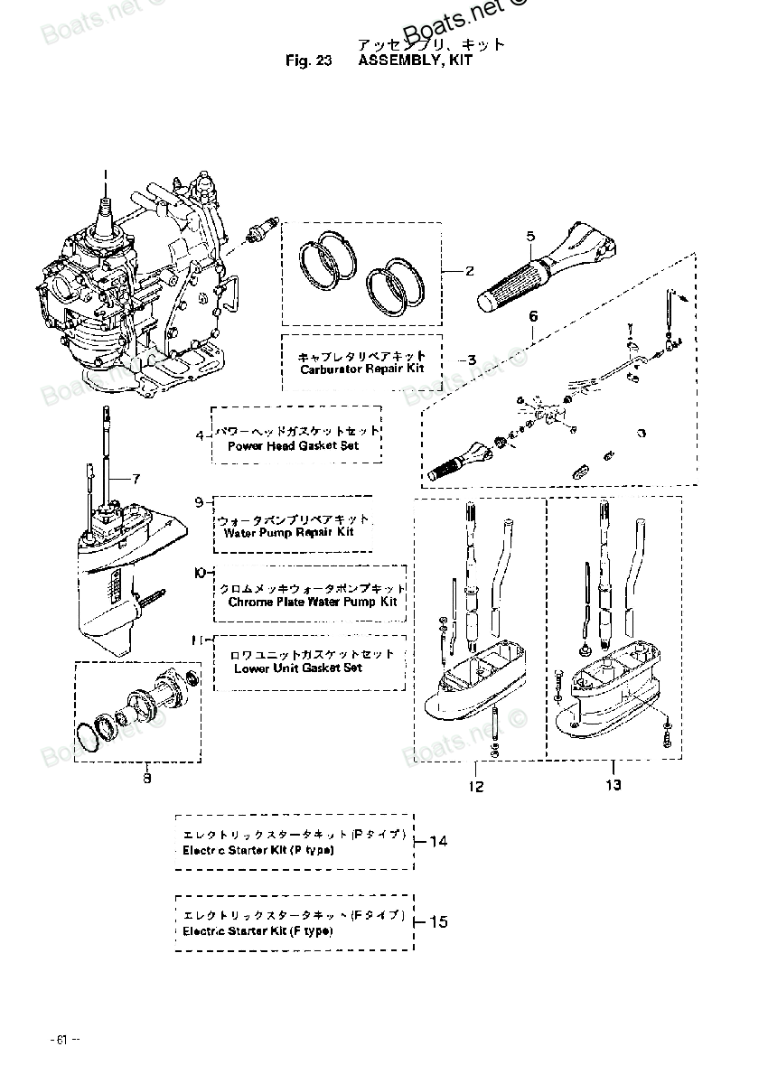
348-65025-0 GUIDE PLATE, WATER PUMP Tohatsu
M25C3, M30A4, M40C, MFS25A, MFS25B, MFS30A, MFS30B
GUIDE

Price: query
Rating:
You can buy parts:
As an associate, we earn commssions on qualifying purchases through the links below

$4.85
19-12-2023
SG: ITACO STORE
Boat Water Pump Guide Impeller Plate 348-65025 345-65025 161592 For Tohatsu Nissan Mercury Outboard M NS F 25HP-40HP 2/4-stroke
ITACO 100% Aftermarket Made in Taiwan || For Tohatsu Nissan Outboard part number: 348-65025-0 M, 345-65025-0, 345-65025-1 (IMPT: check OEM part number before purchase!!) || For Mercury Mercruiser Quicksilver part number:161592 || Guide Water Pump Impeller Plate || Boat Motor for Outboard Engine
ITACO 100% Aftermarket Made in Taiwan || For Tohatsu Nissan Outboard part number: 348-65025-0 M, 345-65025-0, 345-65025-1 (IMPT: check OEM part number before purchase!!) || For Mercury Mercruiser Quicksilver part number:161592 || Guide Water Pump Impeller Plate || Boat Motor for Outboard Engine
Number on catalog scheme: 9
Tohatsu entire parts catalog list:
- ASSEMBLY KIT » 348-65025-0
- TRANSMISSION - WATER PUMP » 348-65025-0
- ASSEMBLY KIT » 348-65025-0
- TRANSMISSION - WATER PUMP » 348-65025-0
- GEAR CASE (PROPELLER SHAFT) » 348-65025-0
- ASSEMBLY KIT » 348-65025-0
- GEAR CASE (DRIVE SHAFT) » 348-65025-0
- DRIVE SHAFT & WATER PUMP » 348-65025-0
- ASSEMBLY KIT » 348-65025-0
- ASSEMBLY KIT » 348-65025-0
- DRIVE SHAFT & WATER PUMP » 348-65025-0
- ASSEMBLY KIT » 348-65025-0
- ASSEMBLY KIT » 348-65025-0
Information:
The following adjustment procedure must be strictly followed. Any other method of adjusting the slave piston clearance is not authorized and may result in serious engine and/or engine brake damage.
The slave piston adjustment must be made when the engine is stopped and the engine is cold. Before the Slave Piston Lash can be adjusted, the exhaust valves must be in a closed position. Note: The following procedure is used for Model C336 Compression brakes only.Use the following procedure in order to adjust cylinders 1, 3, and 5:
Put the No. 1 piston at the top center position (TC) on the compression stroke. Refer to Testing and Adjusting, "Finding Top Center Compression Position For No. 1 Piston".
Illustration 1 g00399158
(1) Slave piston adjustment screw (2) Locknut
Loosen locknut (2) .
When the exhaust valves are closed and the rocker arms are loose, turn in slave piston adjustment screw (1) until the slave piston contacts the cap of the valve stem.
Illustration 2 g00370713
(3) 149-0114 Valve Adjustment Gauge (4) Wrench
Place the valve adjustment gauge (3) over slave piston adjustment screw (1) and locknut (2) so that the "A" mark is in line with wrench (4) .
Hold valve adjustment gauge (3) in position. Turn wrench (4) in the counterclockwise direction from the "A" mark to the "B" mark on the gauge. This will provide a clearance for the slave piston of 0.89 mm (0.035 inch). See Table 1 for slave piston lash settings.
Tighten the locknut to a torque of 35 N m (25 lb ft).
Repeat this procedure for cylinders 3 and 5.
Remove the timing bolt, and turn the flywheel by 360 degrees in the direction of the engine's rotation. This will put No. 6 piston at the top center position (TC) on the compression stroke. Install the timing bolt in the flywheel.
Repeat Steps 2 through 5 for adjusting cylinders 2, 4, and 6.
Remove the timing bolt from the flywheel when all adjustments have been made.Note: The following procedure is used for model 336A Compression brakes only.
The following adjustment procedure must be strictly followed. Any other method of adjusting the slave piston clearance is not authorized and may result in serious engine and/or engine brake damage.
The slave piston adjustment must be made when the engine is stopped and the engine is cold. Before the Slave Piston Lash can be adjusted, the exhaust valves must be in a closed position. Use the following procedure in order to adjust cylinders 1, 3, and 5:
Put the No. 1 piston at the top center position (TC) on the compression stroke. Refer to Testing and Adjusting, "Finding Top Center Compression Position For No. 1 Piston".
Illustration 3 g00399158
(1) Slave piston adjustment screw (2) Locknut
Loosen locknut (2) .
Illustration 4 g00729194
(5) 149-0059 Feeler Gauge (6) Valve cap (7) Slave piston foot
When the exhaust valves are closed and the rocker arms are loose, place Feeler gauge (5) between valve cap (6) and slave piston foot (7) .
Illustration 5 g00728360
(A) Incorrect (B) CorrectNote: Ensure that the feeler gauge is inserted completely under both feet of the piston.
Turn the adjusting screw until a slight drag is felt.This will provide a clearance for the slave piston of 3.43 mm (0.135 inch). See Table 1 for slave piston lash settings.
Hold the adjusting screw. Torque the locknut to a torque of 35 N m (25 lb ft).
Repeat Steps 2 through 5 for adjusting cylinders 2, 4, and 6.
Remove the timing bolt from the flywheel when all adjustments have been made.
Parts guide Tohatsu:
346-63722-2
346-63722-2 GUIDE PLATE
M15D2, M18E2, M25C3, M30A4, M40C, M40D2, M40D2, M40D2, M50D2, M60C, M70C, M9.9D2
361-65239-0
336-05014-0
3R0-65025-0