345-65021-0 IMPELLER, WATER PUMP Tohatsu
M25C3, M30A4, M40C, MFS25A, MFS25B, MFS25B, MFS25B, MFS30A, MFS30B, MFS30B
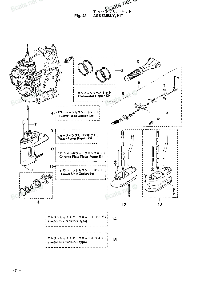
IMPELLER

Price: query
Rating:
You can buy parts:
As an associate, we earn commssions on qualifying purchases through the links below

LOAwYAY for 25P 30P 35P 40P 47-16154-1 47-161541 Water Pump Impeller 345-65021-0 18-8923 for Outboard Engine
LOAwYAY Applicable models: Suitable for 2-stroke 40-50P, M40D / M40D2 / M50D / M50D2 and 2-stroke TLDI30-50P, MD30B2 / MD40B / MD40B2 / MD50A / MD50B2 and other models, with strong compatibility to meet different needs. || Dimensions: The outer diameter of the impeller is 44mm, the inner shaft socket diameter is 17mm, and the depth/height/width is 20mm, which is suitable for a variety of water pump systems to ensure stable . || Part number: The water pump impeller number is 345-65021-0, which is convenient for you to quickly find and replace, and meets various repair and replacement needs. || Effective : The use of quality materials ensures that the water pump impeller works stably, which helps to optimize the performance of the engine cooling system. || design: The design is sturdy and , suitable for a variety of environments, ensuring stability in long-term use.
LOAwYAY Applicable models: Suitable for 2-stroke 40-50P, M40D / M40D2 / M50D / M50D2 and 2-stroke TLDI30-50P, MD30B2 / MD40B / MD40B2 / MD50A / MD50B2 and other models, with strong compatibility to meet different needs. || Dimensions: The outer diameter of the impeller is 44mm, the inner shaft socket diameter is 17mm, and the depth/height/width is 20mm, which is suitable for a variety of water pump systems to ensure stable . || Part number: The water pump impeller number is 345-65021-0, which is convenient for you to quickly find and replace, and meets various repair and replacement needs. || Effective : The use of quality materials ensures that the water pump impeller works stably, which helps to optimize the performance of the engine cooling system. || design: The design is sturdy and , suitable for a variety of environments, ensuring stability in long-term use.

Suitable for 25 30 35 40 HP Outboard Motor Water Pump Impeller 345-65021-0
SeXeaoI Applicable models: Suitable for 25HP, 30HP, 35HP, 40HP outboard engines, covering two-stroke and four-stroke models, meeting the needs of various equipment. || OEM number: Corresponding to 345-65021-0, 3R0-65021-0, 18-8923, 777-345, 500382 and other numbers, convenient for quick matching and replacement. || Product specifications: The outer diameter of the impeller is 44 mm, the height is 20 mm, and the inner shaft insertion diameter is 17 mm, which meets the common outboard engine installation standards. || Package content: The set contains a water pump impeller, and the actual product is consistent with the picture display, which is convenient for confirming the accessories. || Type description: Suitable for two-stroke M25, M30, M35, M40 and four-stroke MFS25, MFS30 outboard equipment, with a wide range of applications. || Material description: It uses a combination of chloroprene rubber and nylon hub, with a stable structure and adaptable to the use environment of outboard engines.
SeXeaoI Applicable models: Suitable for 25HP, 30HP, 35HP, 40HP outboard engines, covering two-stroke and four-stroke models, meeting the needs of various equipment. || OEM number: Corresponding to 345-65021-0, 3R0-65021-0, 18-8923, 777-345, 500382 and other numbers, convenient for quick matching and replacement. || Product specifications: The outer diameter of the impeller is 44 mm, the height is 20 mm, and the inner shaft insertion diameter is 17 mm, which meets the common outboard engine installation standards. || Package content: The set contains a water pump impeller, and the actual product is consistent with the picture display, which is convenient for confirming the accessories. || Type description: Suitable for two-stroke M25, M30, M35, M40 and four-stroke MFS25, MFS30 outboard equipment, with a wide range of applications. || Material description: It uses a combination of chloroprene rubber and nylon hub, with a stable structure and adaptable to the use environment of outboard engines.

ZiKueeo Universal 345-65021 Water Pump Impeller Compatible Outboard Marine Motor 25HP 30HP 40HP 345-65021-0 18-8923 500382 3R0-65021
ZiKueeo Compatible models: Suitable for 345-65021, compatible with 25HP, 30HP, 40HP marine engines, suitable for 345-65021-0, 18-8923, 500382, 3R0-65021 models. || Size adaptation: The pump impeller is precisely matched with the relevant models to ensure effective water flow and improve the performance of the pump. || Specification standards: Manufactured in accordance with industry standards to ensure consistency with related components and provide long-lasting and stable pump working effects. || Widely compatible: Suitable for marine engines of multiple power levels to meet different needs and improve engine cooling effects. || Durable design: Adopts corrosion-resistant and wear-resistant materials to adapt to the marine environment and ensure long-term use. || Quantity selection: Provide flexible quantity selection to meet different maintenance or replacement needs, convenient and flexible procurement
ZiKueeo Compatible models: Suitable for 345-65021, compatible with 25HP, 30HP, 40HP marine engines, suitable for 345-65021-0, 18-8923, 500382, 3R0-65021 models. || Size adaptation: The pump impeller is precisely matched with the relevant models to ensure effective water flow and improve the performance of the pump. || Specification standards: Manufactured in accordance with industry standards to ensure consistency with related components and provide long-lasting and stable pump working effects. || Widely compatible: Suitable for marine engines of multiple power levels to meet different needs and improve engine cooling effects. || Durable design: Adopts corrosion-resistant and wear-resistant materials to adapt to the marine environment and ensure long-term use. || Quantity selection: Provide flexible quantity selection to meet different maintenance or replacement needs, convenient and flexible procurement
Number on catalog scheme: 9
Tohatsu entire parts catalog list:
- ASSEMBLY KIT » 345-65021-0
- TRANSMISSION - WATER PUMP » 345-65021-0
- ASSEMBLY KIT » 345-65021-0
- TRANSMISSION - WATER PUMP » 345-65021-0
- GEAR CASE (DRIVE SHAFT) » 345-65021-0
- ASSEMBLY KIT » 345-65021-0
- DRIVE SHAFT & WATER PUMP » 345-65021-0
- ASSEMBLY KIT » 345-65021-0
- DRIVE SHAFT & WATER PUMP » 345-65021-0
- LOWER UNIT » 345-65021-0
- LOWER UNIT » 345-65021-0
- ASSEMBLY KIT » 345-65021-0
- DRIVE SHAFT & WATER PUMP » 345-65021-0
- DRIVE SHAFT & WATER PUMP » 345-65021-0
- LOWER UNIT » 345-65021-0
Information:
Illustration 1 g00529671
System Schematic For Engine Oil Temperature Sensor (EOTS)
The EMCP II+ system monitors the engine coolant temperature in order to protect the engine from a coolant temperature problem. The coolant temperature sensor is mounted in the water jacket. The exact location of the engine coolant temperature sensor varies depending on the engine model.The sensor is powered by an 8 volt sensor supply from the GSC+. The coolant temperature signal is a pulse width modulated signal. The base frequency of the signal is 455 Hz (370 to 550 Hz). As temperature changes, the duty cycle of the signal varies from 10 to 95 percent.
−40°C (−40°F) is approximately 10% of the duty cycle, which is approximately 1.0 DCV.
135°C (275°F) is approximately 93% of the duty cycle.Note: The GSC+ is usually programmed to treat an oil temperature sensor problem as an alarm fault. The factory default for P004 is 0. The GSC+ may be programmed to shutdown for an oil temperature sensor fault. P004 is 1 for a shutdown. The operator is not required to press the "Alarm Codes" key in order to view the CID 175 FMI 2. The CID 175 FMI 2 is automatically shown on the upper display.The possible causes of a CID 175 FMI 2 are listed below:
The base frequency of the sensor signal is beyond accepted limits.
The duty cycle of the sensor signal is beyond accepted limits.Begin performing these procedures only when CID 175 FMI 2 is showing and the "DIAG" indicator is FLASHING on the upper display. The GSC+ treats a CID 175 FMI 2 as an alarm fault. Active alarm faults are shown on the display when the "Alarm Codes" key is pressed. The engine control switch (ECS) must be in any position except the OFF/RESET position. For an inactive fault, the problem may be intermittent. In order to troubleshoot an inactive fault, use the preceding system schematic. See Testing And Adjusting, "Electrical Connector - Inspect". Clear the diagnostic code from the fault log after troubleshooting is complete.Note: This procedure can be replaced by troubleshooting the sensor signal with a meter that is capable of measuring frequency and duty cycle. See Testing And Adjusting, "Pulse Width Modulated (PWM) Sensor - Test".Note: If a Sensor Supply fault (CID 269) is active, correct the fault prior to proceeding with this procedure.Test Step 1. CHECK THE GSC+ AND THE HARNESS.
Make sure that CID 175 FMI 2 is showing on the display.
Turn the ECS to the OFF/RESET position.
Disconnect the sensor from the engine harness. The sensor remains fastened to the engine.
Turn the ECS to the STOP position.
Press the "Alarm Codes" key. The "Alarm Codes" key does not need to be pressed for shutdown faults. Check if the CID 175 FMI 2 is not showing. This means that the CID 175 FMI 2 is inactive. Check if the CID 175 FMI 3 is now showing. CID 175 FMI 3 is now active. Expected Result:CID 175 FMI 2 is not showing. The diagnostic code is inactive. CID 175 FMI 3 is showing. The diagnostic code is active.Results:
OK - The GSC+ and the harness function properly. Therefore, the sensor has failed. Replace the sensor. Repair: For more information, refer to Testing and Adjusting, "Pulse Width Modulated (PWM) Sensor - Test".STOP
NOT OK - The CID 175 FMI 2 fault is showing. The harness or the GSC+ has failed. Proceed to Test Step 2.Test Step 2. CHECK THE GSC+.
Turn the ECS to the OFF/RESET position.
Disconnect the harness connector from the GSC+.
Turn the ECS to the STOP position.
Press the "Alarm Codes" key.
Check if CID 175 FMI 2 is no longer showing. Check if CID 175 FMI 3 is now showing. Expected Result:CID 175 FMI 2 is not showing. The diagnostic code is inactive. CID 175 FMI 3 is now showing. The diagnostic code is active.Results:
OK - The GSC+ functions properly. Therefore, the signal wire has failed in the harness. Troubleshoot the signal wire in the harness between the sensor connector and the GSC+ connector. Also check the electrical connectors and terminals.Repair: For additional information, refer to Testing And Adjusting, "Electrical Connector - Inspect".STOP
NOT OK - The CID 175 FMI 2 is still showing. Repair: The GSC+ may have failed. It is unlikely that the GSC+ has failed. Exit this procedure and perform this entire procedure again. If the problem remains, replace the GSC+. See Testing And Adjusting, "EMCP Electronic Control (Generator Set) - Replace". STOP
Parts impeller Tohatsu:
3R0-65021-0
