21665539 Bracket Volvo.Penta
TAD550GE; TAD551GE; TAD750GE
Bracket

Price: query
Rating:
Number on catalog scheme: 9
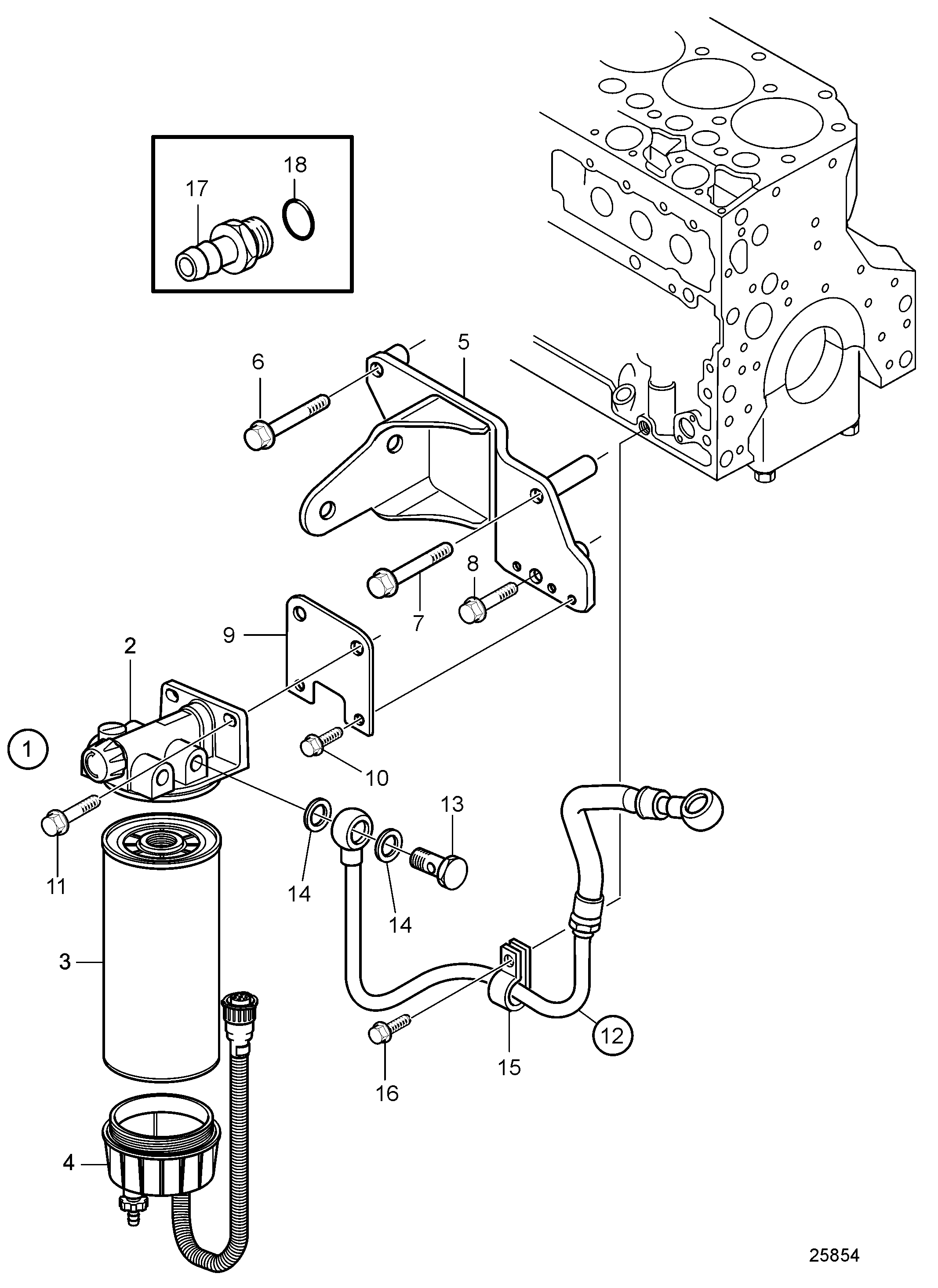
Compatible models:
TAD550GE; TAD551GE; TAD750GE
Volvo.Penta
Volvo Penta entire parts catalog list:
- Fuel Pre Filter and Water Separator » 21665539
Information:
Illustration 1 g00295370
Bolt tightening sequence for the cylinder head
Use the following procedure in order to tighten the cylinder head bolts:
Put engine oil on the threads of the bolts and the nuts. Tighten bolts (1) through bolts (22) in a numerical sequence in Illustration 1. Torque for the bolts ... 110 N m (81 lb ft)
Tighten bolts (1) through bolts (22) again in a numerical sequence. Torque for bolts ... 110 N m (81 lb ft)
Rotate bolts (1) through bolts (22) in a numerical sequence to the following values:
Tighten the bolts of short length "S" to the following value. Rotate the bolts in a clockwise direction: ... 150 degrees
Tighten the bolts of medium length "M" to the following value. Rotate the bolts in a clockwise direction: ... 180 degrees
Tighten the bolts of long length "L" to the following value. Rotate the bolts in a clockwise direction: ... 210 degrees
Illustration 2 g00295371
Bolts, nuts, and components of the cylinder head
(1) Tighten the nuts that hold fuel injectors to the following torque: ... 12 N m (10 lb ft)Note: When the fuel injection nozzle is removed, the following items must be replaced: dust seal and seat washer. (2) Tighten the nuts for fuel line to the following torque: ... 18 N m (13 lb ft) (3) Tighten the bolts that hold the rocker shaft to the cylinder head to the following torque: Begin tightening the inner bolts. Then tighten the bolts by working toward the end of the shaft. Cast iron or steel bracket ... 75 N m (55 lb ft)Aluminum bracket ... 40 N m (30 lb ft) (4) Valve lash Inlet ... 0.20 mm (.008 inch)Exhaust ... 0.45 mm (.018 inch) (5) Maximum permissible nozzle projection below cylinder head face after resurfacing ... 4.45 mm (.175 inch)Maximum allowance for resurfacing ... 0.30 mm (.012 inch) (6) Depth of new cylinder head ... 102.79 to 103.59 mm (4.047 to 4.078 inch)Minimum depth of cylinder head after resurfacing ... 102.48 mm (4.035 inch)
Illustration 3 g00295372
Positions for measuring the bow of the cylinder head (typical example)
Maximum permissible amount of bow (curve of cylinder head) Naturally aspirated engines A ... 0.08 mm (.003 inch)B ... 0.15 mm (.006 inch)C ... 0.15 mm (.006 inch)Turbocharged engines A ... 0.13 mm (.005 inch)B ... 0.25 mm (.010 inch)C ... 0.25 mm (.010 inch)Tighten the bolts of the inlet manifold (not shown) to the following torque: ... 44 N m (32 lb ft)Tighten exhaust manifold nuts (not shown) to the following torque: Plated ... 44 N m (32 lb ft)Plain ... 50 N m (37 lb ft)Type 2 Engines and 7BJ Engines
Note: For a complete description of Type 1 and Type 2 engines, refer to the Specifications Module, "Engine Design" for more information.
Illustration 4 g00295370
Bolt tightening sequence for the cylinder head
Use the following procedure in order to tighten the cylinder head bolts:
Put engine oil on the threads of bolts. Tighten bolts (1) through bolts (22) in a numerical sequence in Illustration 4. Torque for bolts ... 110 N m (81 lb ft)
Tighten bolts (1) through bolts (22) again in a numerical sequence. Torque for bolts ... 110 N m (81 lb ft)
Rotate bolts (1) through bolts (26) in a numerical sequence to the following values:
Tighten the bolts of short length "S" to the following value. Rotate the bolts in a clockwise direction: ... 150 degrees
Tighten the bolts of medium length "M" to the following value. Rotate the bolts in a clockwise direction: ... 180 degrees
Tighten the bolts of long length "L" to the following value. Rotate the bolts in a clockwise direction: ... 210 degrees
Illustration 5 g00295373
Bolts, nuts, and components of the cylinder head
Note: When the fuel injection nozzle is removed, the following items must be replaced: dust seal and seat washer. (1) Tighten the bolts that hold the rocker shaft to the cylinder head to the following torques: Begin tightening the inner bolts. Then tighten the bolts by working toward the end of the shaft. Cast iron or steel bracket ... 75 N m (55 lb ft)Aluminum bracket ... 40 N m (30 lb ft) (2) Valve lash Inlet ... 0.20 mm (.008 inch)Exhaust ... 0.45 mm (.018 inch) (3) Maximum permissible nozzle projection below cylinder head face after resurfacing ... 4.45 mm (.175 inch)Maximum allowance for resurfacing ... 0.30 mm (.012 inch) (4) Depth of new cylinder head ... 102.79 to 103.59 mm (4.047 to 4.078 inch)Minimum depth of cylinder head after resurfacing ... 102.48 mm (4.035 inch)
Illustration 6 g00295372
Positions for measuring the bow of the cylinder head (typical example)
Maximum permissible amount of bow (curve of the cylinder head) A ... 0.08 mm (.003 inch)B ... 0.15 mm (.006 inch)C ... 0.15 mm (.006 inch)Tighten the bolts for the inlet manifold (not shown) to the following torque: ... 44 N m (32 lb ft)Tighten the nuts for the exhaust manifold (not shown) to the following torque: Plated ... 44 N m (32 lb ft)Plain ... 50 N m (37 lb ft)
Parts bracket Volvo Penta:
21156350
20450997
20450997 Bracket
TAD520GE; TAD720GE; TAD721GE, TAD520VE; TAD720VE; TAD721VE, TAD550GE; TAD551GE; TAD750GE, TAD560VE; TAD561VE; TAD761VE, TAD734GE, TAD750VE; TAD760VE, TD420VE; TAD420VE; TAD620VE, TD520GE; TAD530GE; TAD531GE
21004700
21888902
21665202
21140359
21030166
22232497